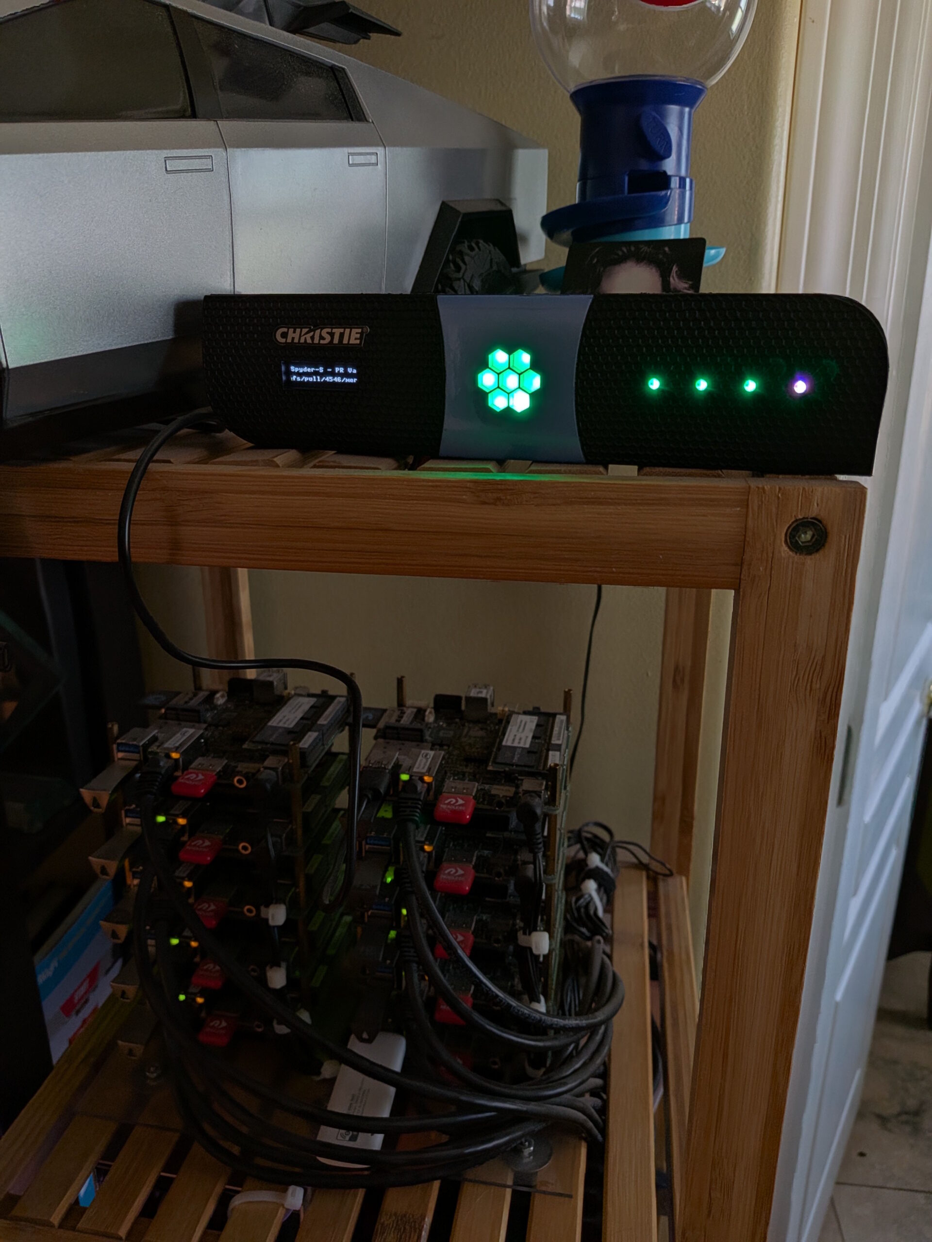
The finished panel, showing a green build

Building a Build Monitor out of a Salvaged Quad-T Front Panel

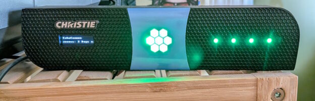
The finished panel, showing a green build

How this one got started

Every so often a project starts with a piece of hardware that somebody else has already given up on. This one started in a pile headed for the trash.

The part that caught my eye was the front panel off a Christie Phoenix Quad-T, which has been end-of-support for a while now. The chassis itself was done, but it has a neat front-panel — a half-rack wide and one rack unit tall textured plate with curved corners, a little window for a 128×32 OLED, a strip of holes for indicator LEDs, and a frosted hexagon dead center.

For a while it just sat on the bench while I tried to decide what it should be. The OLED and the LED board were still intact, which meant whatever I built could show both text and color. The obvious answer, the one I kept coming back to, was a build monitor. At work we’ve got a handful of Azure DevOps pipelines that I care about, and “is anything red right now?” is a question I answer by opening a browser tab and looking at a dashboard. A physical thing on a shelf that just tells me seemed like a better answer.

A couple of decisions fell out of that pretty quickly:

  • The center hexagon was too good to waste on a single LED, so I added a 7-pixel NeoPixel Jewel behind it. Seven pixels, seven pipelines. To diffuse it I cut two layers out of a gallon milk jug and stacked them behind the hexagon window — I fully intended to replace that with something proper later, and of course I never did, because it works perfectly.
  • It had to be wireless. A device that needs an Ethernet run is a device that lives wherever the Ethernet run is, and I wanted this thing to be able to sit anywhere.
  • I have a bunch of small embedded boards lying around, and landed on using a Raspberry Pi Pico W running MicroPython. It’s cheap, tiny, has WiFi built in, and is quick to iterate on.
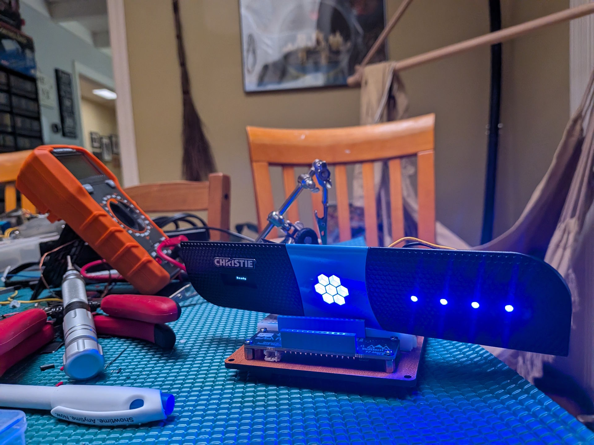
Early bring-up on the bench
Early bring-up on the dining room table

That’s the first time it really looked like something. I had it cycling through some colors for testing ahead of wiring up the real application, but everything worked and looked pretty sweet (albeit crazy bright which I ended up dialing down in software later).

Building the hardware

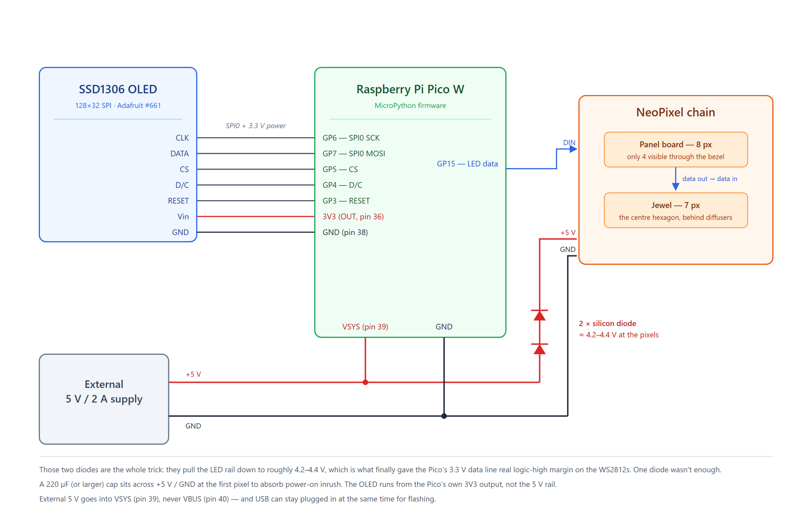
Here’s the whole thing on paper:

Wiring diagram
Wiring diagram

Parts in the panel

  • Raspberry Pi Pico W — the brains, and about $6.
  • Adafruit SSD1306 128×32 SPI OLED (#661) — this is the stock panel used in the panel’s window. It now runs off the Pico’s 3.3V output.
  • Adafruit NeoPixel Stick — 8 WS2812 pixels, though only 4 of them line up with holes in the bezel. The other 4 are wired, powered, and permanently invisible (more on that later).
  • An Adafruit NeoPixel Jewel — 7 pixels, and exactly the right size to fill the center hexagon.
  • Two silicon diodes — cheap, and the entire reason this works. More below.
  • A 220µF (or larger) electrolytic cap — across 5V/GND at the first pixel, to soak up power-on inrush.
  • A 5V / 2A external supply — the Pico W pulls 100-150mA with WiFi spikes on top, and 11 NeoPixels at full white can hit ~660mA. 2A leaves comfortable headroom.

The OLED is straightforward SPI — clock, data, chip select, D/C, reset, plus 3.3V and ground straight off the Pico. The NeoPixels are a single data line off GPIO15, daisy chained from the panel’s original board into the Jewel.

Power is where it gets slightly more interesting. Rather than run the Pico off USB and the LEDs off a separate supply, I run one 5V supply and “T” it: one leg to the LED chain, one leg to the Pico’s VSYS pin. That’s pin 39, and it’s the input the onboard regulator is designed to accept external power on. Not VBUS (pin 40) — that one’s tied to the USB rail, and I learned that feeding it can damage the Pi board. Splitting a single supply this way also hands you a shared ground for free, which the NeoPixels very much require. And because there’s a diode between VBUS and VSYS on the Pico, you can leave USB plugged in at the same time while you’re developing without the two supplies fighting which ended up being massively helpful while tweaking the software on this thing.

The diode trick

Here’s the one that I spent a lot of time on and almost gave up over. WS2812 pixels want a logic-high somewhere north of 0.7 × VDD. The Pico’s GPIO is 3.3V. On a true 5V rail, that’s under spec, and the symptom is maddening: the pixels get data — I could see it on my oscilloscope — but they mostly ignore it. Sometimes the first pixel lights, usually nothing, and sometimes it worked fine for a few minutes and then stopped.

The fix that finally worked was two silicon diodes in series in the LED’s +5V feed — not in the data line — dropping the pixel rail to roughly 4.2-4.4V and giving that 3.3V signal actual margin. I tried one diode first, and it almost worked, which is the worst outcome. Forward voltage sags at low current, and this chain spends most of its life dim or idle, so a single ~0.6-0.7V drop kept wandering back out of spec. Two diodes, rock solid ever since. This is apparently common knowledge for smart people, and I saw a lot of posts online about it (after circling in on it by chatting with ChatGPT).

Worth checking your supply too, incidentally — some USB bricks like the one I’m using measure 5.4-5.5V under light load, which makes the margin problem worse than the initial math would suggest.

About that soldering

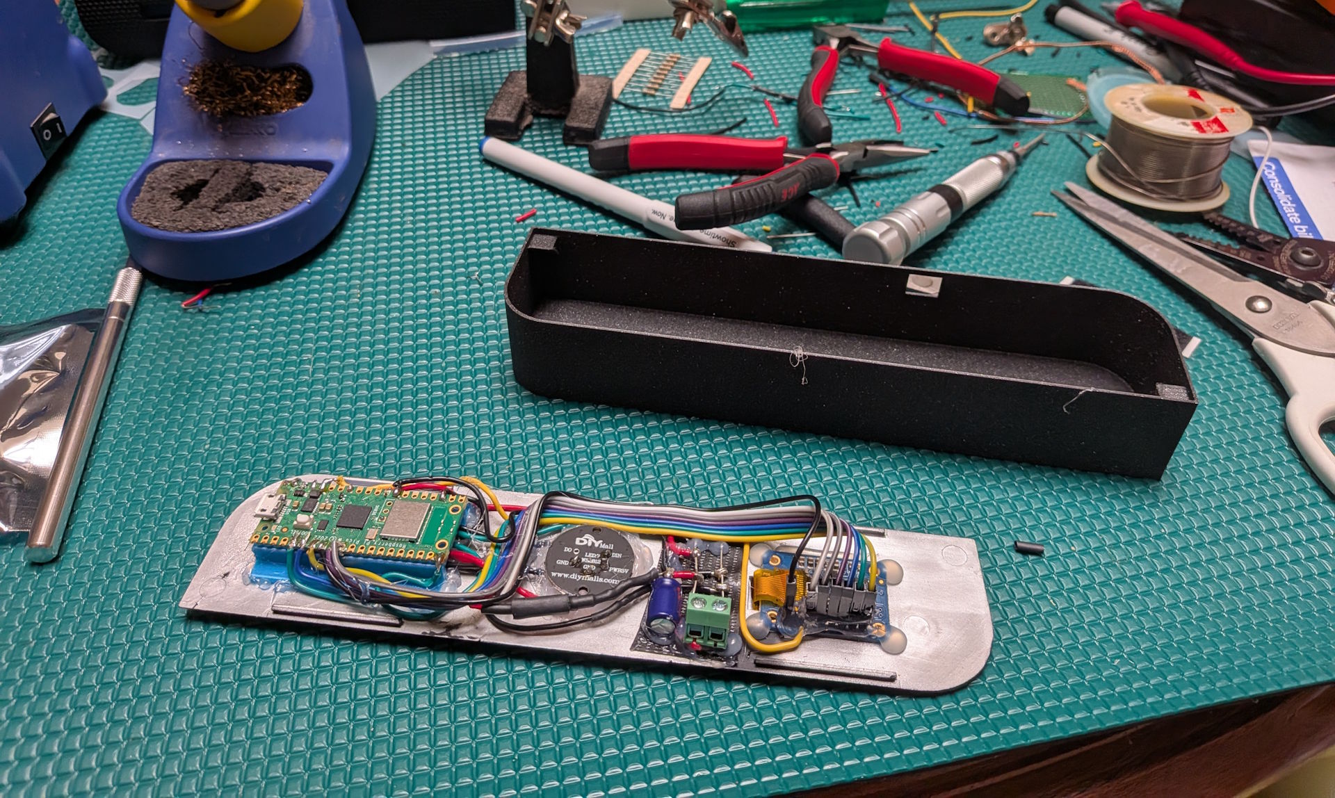
The board on the bench, mid-assembly

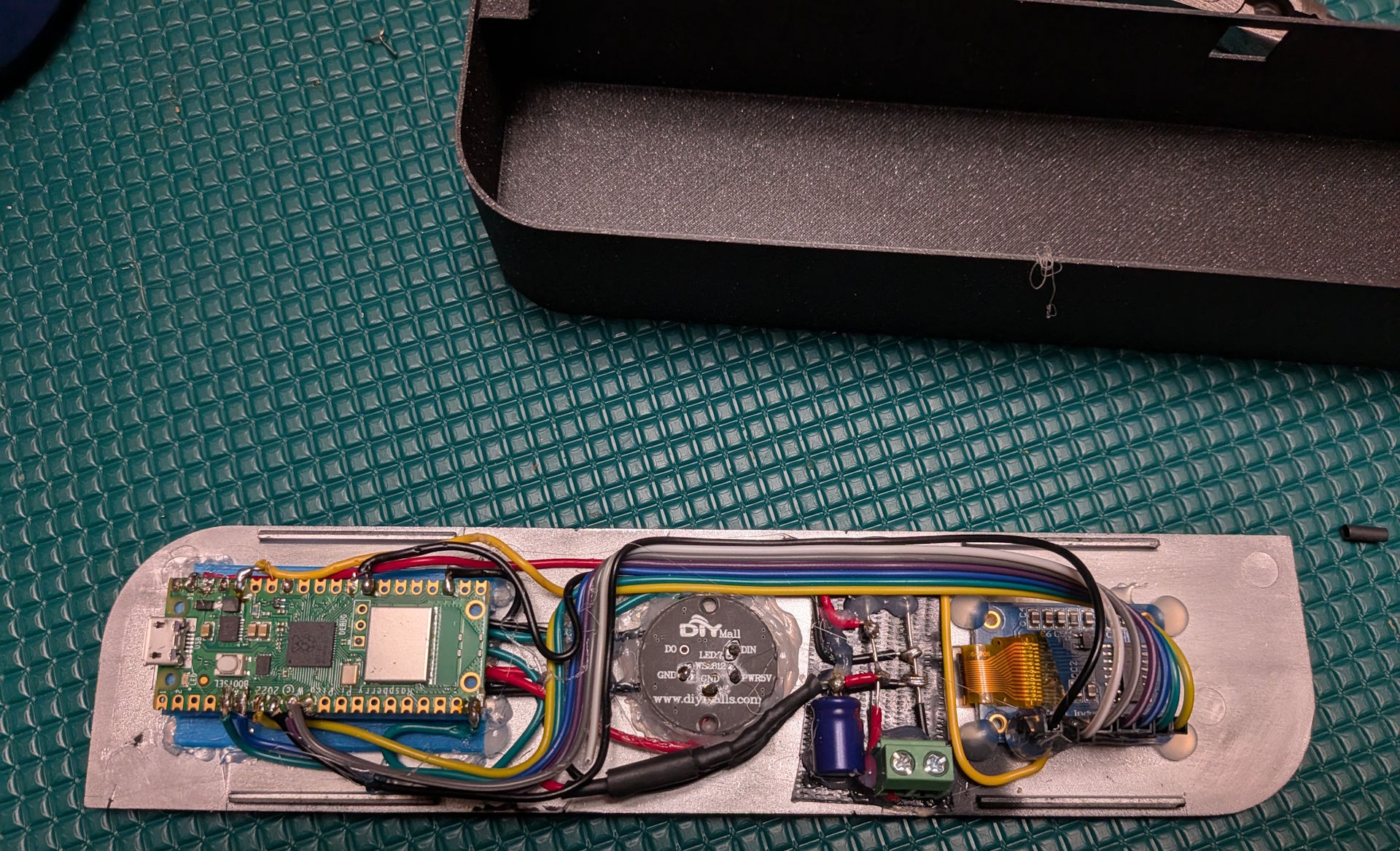
The pictures above and below show the wired-up mess at the back of the panel, and admittedly it’s messy. Every joint on that Pico is a small monument to enthusiasm exceeding technique — blobby, over-tinned, and held in position by optimism and hot glue. In my defense: the panel’s backing plate is the mounting surface, everything has to sit flat enough to still fit behind a curved bezel, and there was not a lot of room in there to be elegant.

The back of the assembled panel

It doesn’t look like much, but it hasn’t dropped a connection yet, so I’ve decided it’s a feature.

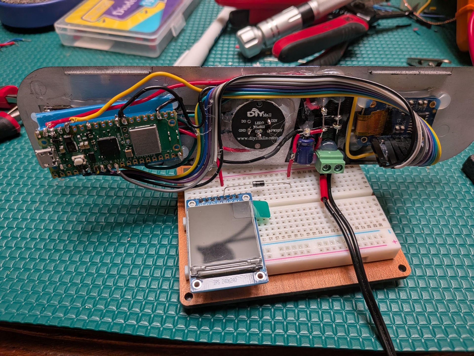
Breadboard testing with a spare display
Breadboard testing with a spare (unrelated) display

I did most of the ugly experimentation using a breadboard — which is where I dialed in that diode business — before committing anything to the panel itself. This picture above was the last part where I was figuring out the diode thing.

3D printing a chassis

The panel is a curved face with nothing behind it, so it needed a body. I designed one in Tinkercad and printed it on my Prusa Core One, which I will take any excuse to mention because I love that printer. Big enclosed build volume, quiet, and it just prints — I’ve stopped thinking about first layers entirely, which is the highest compliment I can pay a 3D printer.

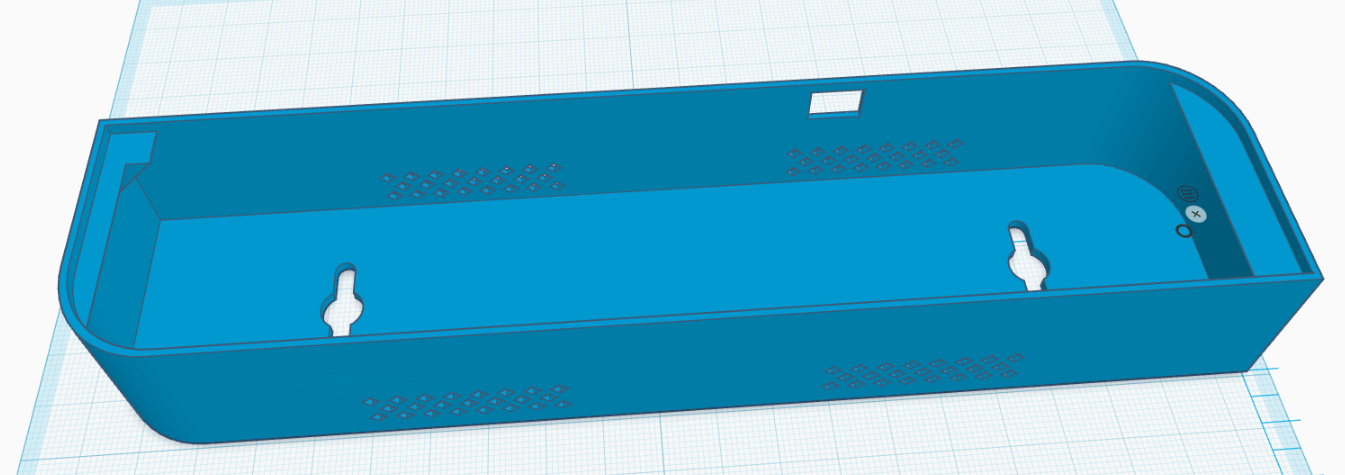
The case design in Tinkercad

The design is deliberately dumb: an open-backed tray that the panel drops onto face-out, with all the electronics hanging down inside it. The panel is held on with velcro rather than screws, which means getting back to the Pico’s USB port is a matter of peeling the face off.

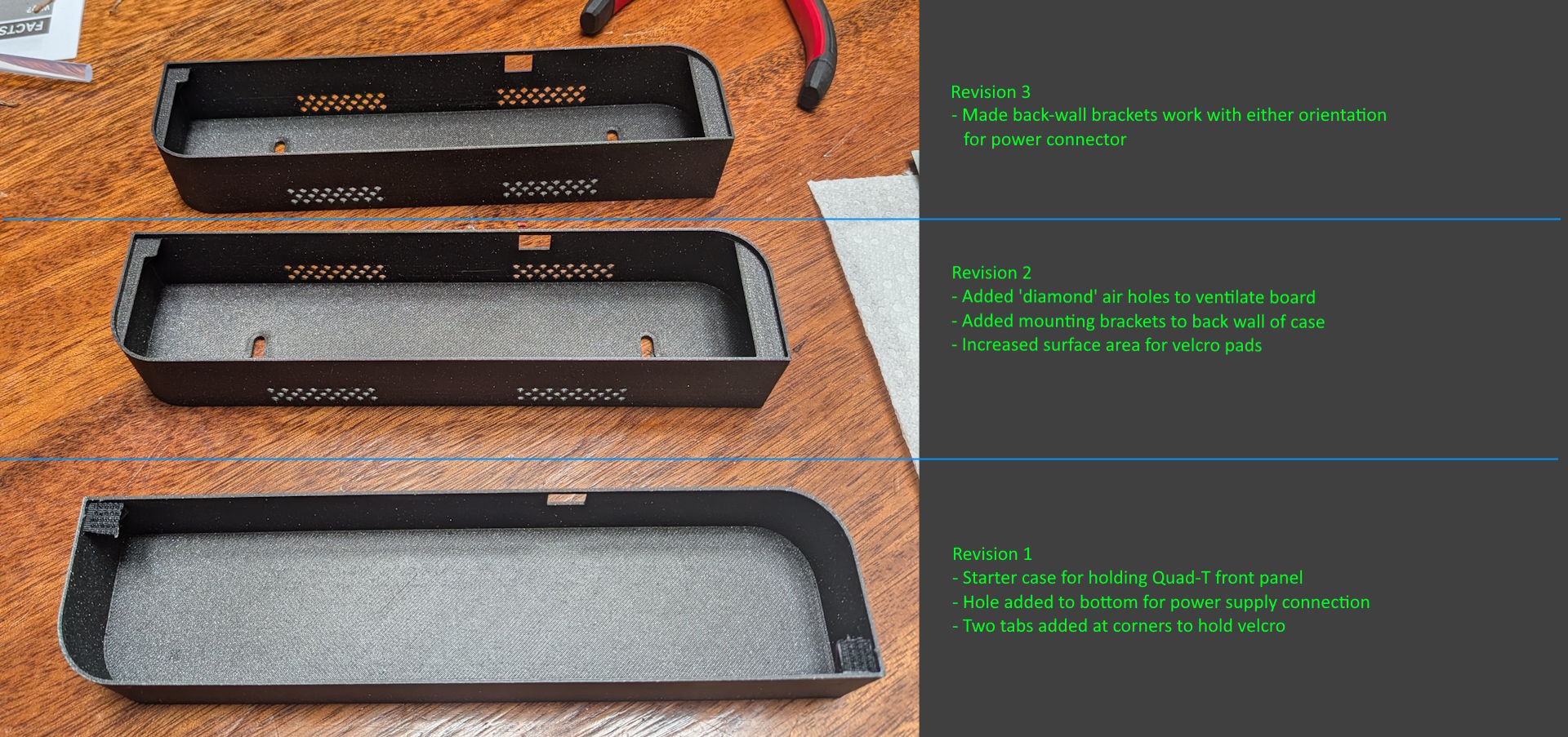
It took three revisions to get right, which I think is about par:

Three printed revisions with notes
  • Revision 1 was the naive version — a tray, a hole in the bottom for the power connector, and two corner tabs to hold velcro. It worked, and immediately told me what was wrong with it.
  • Revision 2 added “diamond” vent holes along the walls so the Pico and the LED chain aren’t sealed in a black plastic box (I noticed it getting warm with the first rev), mounting brackets on the back wall so it can hang, and a lot more flat surface area for the velcro to actually grab.
  • Revision 3 was one specific annoyance: the back-wall brackets only worked with the power connector oriented one way. Reworked them so it hangs correctly with the cable exiting either direction.

The STL is in the repo under case-stl/ if you happen to have a Quad-T front panel lying around, which, statistically, you do not.

Building the software

This is the part I actually enjoyed, and the part where the design decisions mattered.

The firmware should be as dumb as possible

The single most important constraint came from the case: updating this thing is a pain. To reflash it I have to peel the panel off the case, find the USB cable, plug into the Pico, push files with mpremote, and put it all back together. That’s a five minute round trip for even a simple change.

In addition to the physical update process, the reality is that this is a simple IoT device that I might repurpose for anything, and instead of writing tedious code specific for one use case on the target, making it a wireless display and allowing external code to control it feels like the more natural fit. In my case I have a homelab Kubernetes cluster providing more than enough infrastructure to provide messaging and application hosting for the Azure build monitor today and whatever else I might want tomorrow.

So the firmware knows nothing about builds, and it doesn’t know what Azure DevOps is. It stores no credentials beyond the WiFi password, makes no outbound calls to anything but the local MQTT broker, and listens on no inbound ports. It is a generic display device: it connects to WiFi, subscribes to one MQTT topic, and renders whatever JSON shows up there. All the interesting logic lives somewhere I can redeploy in thirty seconds.

That MQTT message contract is the whole design, and it looks roughly like this:

{
  "display": {
    "drawMode": "text2Line",
    "textLine1": "EchoCommon",
    "textLine2": "Success: 2 Days ago",
    "textLine1Align": "left",
    "textLine2AutoScroll": true,
    "oledBurnInProtectionMode": "invertDisplay",
    "oledBurnInProtectionInterval": 60
  },
  "leds": [
    { "r": 0, "g": 255, "b": 0 },
    { "r": 255, "g": 0, "b": 0, "displayMode": "blinkThruBlack", "blinkDuration": 0.75 }
  ],
  "transitionDuration": 2.5,
  "transitionType": "smooth",
  "pixelBrightness": 1.0
}

The goal was high-level but rich — one message should be able to express an entire visual state, and the device should own everything about how that state gets rendered over time. Some of what it can do:

  • Text, one or two lines, each independently left-aligned or centered, and each able to ping-pong scroll if it’s wider than the screen (with a dwell at each end, because scrolling that instantly reverses looks nervous).
  • Raw pixels — you can also just hand it 512 bytes of hex and paint the 128×32 framebuffer yourself.
  • Per-pixel color as a simple array. Position 0 is the first externally visible LED.
  • Transitionsimmediate, smooth (blend from current to target), or thruBlack (fade down, then up into the new color), with a duration.
  • Per-pixel blinkingblink for hard on/off, or blinkThruBlack for a gentle pulse, which is what “this pipeline is running right now” uses.
  • Global brightness, as a single multiplier applied at the moment of writing to hardware.
  • OLED burn-in mitigation, because this display is on 24/7 and may showing nearly the same thing which can get burned into the display permanently. The protocol supports configuration to automatically can invert the panel colors, nudge the text around DVD-logo style, or do nothing.

A few details are worth calling out that evolved organically while I was working on this project. First, the burn-in inversion is motion aware — it only flips once the screen has held genuinely static content for a while, and any new content immediately un-inverts. Since the build monitor rotates through builds anyway, this just looked annoying and served no purpose. The one caveat is that if for some reason the application driving display messages stops updating the panel, the panel will protect itself automatically by using the invertion technique. Second call out is for the hidden LEDs: the panel’s board has 8 pixels but only 4 are visible, so the firmware keeps a map from logical position to physical position and never exposes the hidden ones over MQTT at all. Everything upstream sees a clean chain of 11 addressable pixels and has no idea there’s anything else on the wire. Had I thought about this before hot glueing everything together I would have popped the NeoPixel strip out and drilled 4 extra holes, but it’s simply not worth it to me anymore (but since it’s software configurable if I make another one down the road it’s a simple code change to re-enable it).

The device also publishes its last applied state back to a retained state topic, plus an online/offline status topic wired up as an MQTT Last Will — so anything that cares can tell at a glance whether the panel is actually alive.

Getting real build data to it

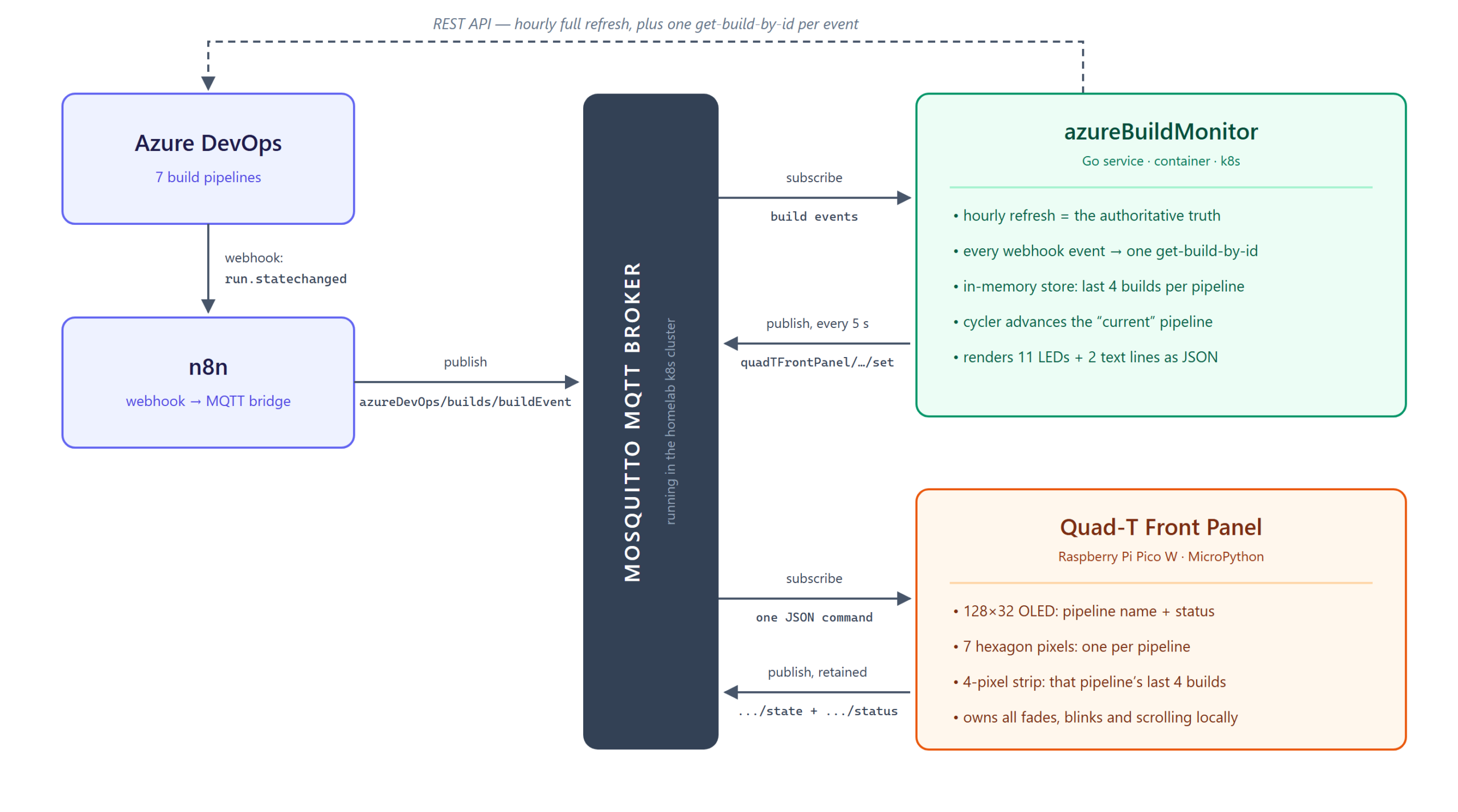
How a build result reaches the panel

With the panel reduced to “renders JSON from a topic”, the rest is a plumbing problem:

  1. Azure DevOps fires a run.statechanged service hook whenever a build changes state.
  2. n8n catches that webhook and republishes it onto my MQTT broker. n8n is already running in my homelab and is very good at exactly this sort of glue, so it saved me from writing and deploying my own webhook receiver just to turn one POST into one MQTT message.
  3. A small Go service (azureBuildMonitor, containerized and running in my k8s cluster) subscribes to that topic, keeps track of the world, and publishes display commands to the panel.

The Go service is where all the real behavior lives, and it works on two timescales at once. It does a full refresh every hour — one API call that fetches the latest 4 builds for every pipeline and overwrites its in-memory view with the authoritative answer. That’s the drift-correction backstop. Then, for responsiveness, every webhook event patches that view in place immediately.

The webhook payload alone turned out not to be trustworthy enough to use directly, which was a fun little discovery: it carries no branch name, and its pipelineId field is actually the run ID rather than the build definition ID that everything else is keyed on. So each event triggers exactly one “get build by ID” call to resolve the truth, and that result is what lands in the store. Events make it fast; the hourly sweep makes it correct.

What you actually see

Every 5 seconds the service publishes a fresh command, and that’s what drives the little show:

  • The 7 hexagon pixels are the pipelines — one each, in a fixed order. Each one always shows its own true status color, so the hexagon as a whole is an at-a-glance health check of everything at once. Green is good, red is failed, blue means running (and pulses through black so it’s obviously live), gray is cancelled.
  • The pipeline being highlighted right now is shown at full brightness while the other six are scaled down to about a quarter. It cycles.
  • The OLED shows the highlighted pipeline’s name on line 1, and cycles line 2 between its status (“Success: 2 Days ago”) and its branch. Once a pipeline has shown all its messages, the highlight moves to the next pipeline and the hexagon follows along.
  • The 4-pixel strip on the right is the highlighted pipeline’s last four builds, newest first. Three green and a red tells you something quite different from four reds, and it’s the fastest possible answer to “is this a blip or a trend?”

Colors and blink timings are all configurable per status, and — this detail matters more than it sounds like it should — configurable separately for the hexagon and the strip. The hexagon sits behind two layers of milk jug and the strip pixels don’t, so the same RGB triple reads as two completely different colors depending on which group it lands on.

Two bugs that weren’t where I thought they were

The panel would connect to MQTT and then get its socket killed immediately, with the broker logging Bad socket read/write and the client reporting a CONNACK “identifier rejected”. I spent an embarrassing amount of time on client IDs. The actual cause: umqtt’s default keepalive is 0, and this particular mosquitto build accepts the CONNECT and then hangs up. Send a real keepalive and ping on it, and everything’s fine.

Worse — and later — well-formed clients started getting rejected with strange, inconsistent errors again. This time it genuinely wasn’t my code. My broker’s Kubernetes Service had externalTrafficPolicy: Cluster, which let MetalLB’s L2 speaker answer ARP from a node that wasn’t the one running the mosquitto pod, forcing an extra kube-proxy SNAT hop that corrupted connections from at least one client. One word changed to Local and it’s been quiet ever since. I’d already rewritten a working MQTT library twice by then, chasing a bug that lived three layers below it.

MQTT Connected
MQTT Connected

So where are we, and what’s next?

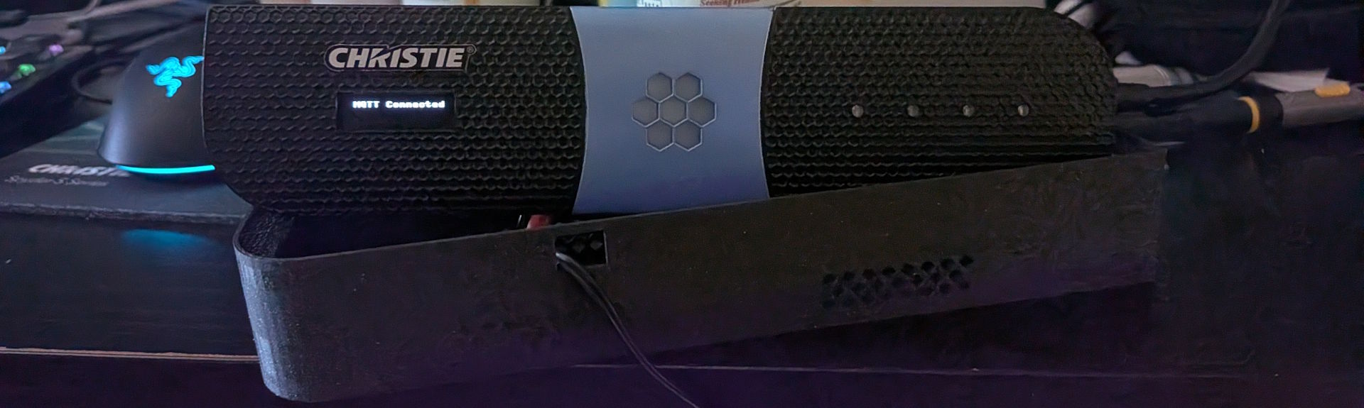
The panel in its natural habitat

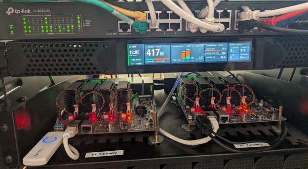
This one landed a lot better than I expected. Most of my projects are fun first and useful second, if at all — this one is genuinely, boringly useful. It sits on a shelf above my little cluster of boards, and every morning I glance at it on my way past and know instantly whether anything needs my attention. No tab, no dashboard, no login.

The unexpected part is what that’s done to my behavior. When build health is a thing sitting in my peripheral vision, a red pixel is a small irritation that I want to make go away, and I fix things the same day instead of discovering them on Thursday. I did not build this expecting to become a more disciplined engineer, and yet.

Next up, most likely: moving off my local broker onto a cloud-hosted message queue, so the panel doesn’t need to live on the same network as the service driving it. Then I can hang it on my cubicle wall at the office, which was sort of the point all along. Or I’ll just build a second one — assuming I can find another junk front panel, which is honestly the hard part.

Everything’s up on GitHub if you want a closer look — firmware, the Go service, the tester CLI, and the case STL:

github.com/dsmithson/quad-t-mqtt-display

If you run into problems or have ideas, filing an issue on the repo is by far the best way to reach me — I have a bad habit of not checking blog comments for months at a time.

Building a Camera Tally Controller for Spyder

A whole 7 years ago I published a blog post and a couple YouTube videos showing a cool Tally (camera relay) system that anyone could make with a $35 Raspberry Pi device and $10 relay board. Back then this was running Windows on the Raspberry Pi 2 – a special stripped-down version of Windows called IoT Core that was designed to run on the Pi.

In seven years, a lot has changed. I started sprouting some gray hairs, Microsoft has all but abandoned Windows IoT Core on the Pi, .Net Core has become a mature way to deploy applications on Linux, and the Pi itself has had a powerful version 4 on the shelves for almost two years now. In this blog post, we’re going to modernize our prior approach and add some cool new features like a front panel display and a configuration/monitoring web interface.

Features and Overview

  • Works with Spyder 200 / 300 / X20 / X80 hardware
  • Works with every major release version of Spyder software
  • Supports different servers and rules per individual tally
  • Built-in web server for remote configuration and monitoring
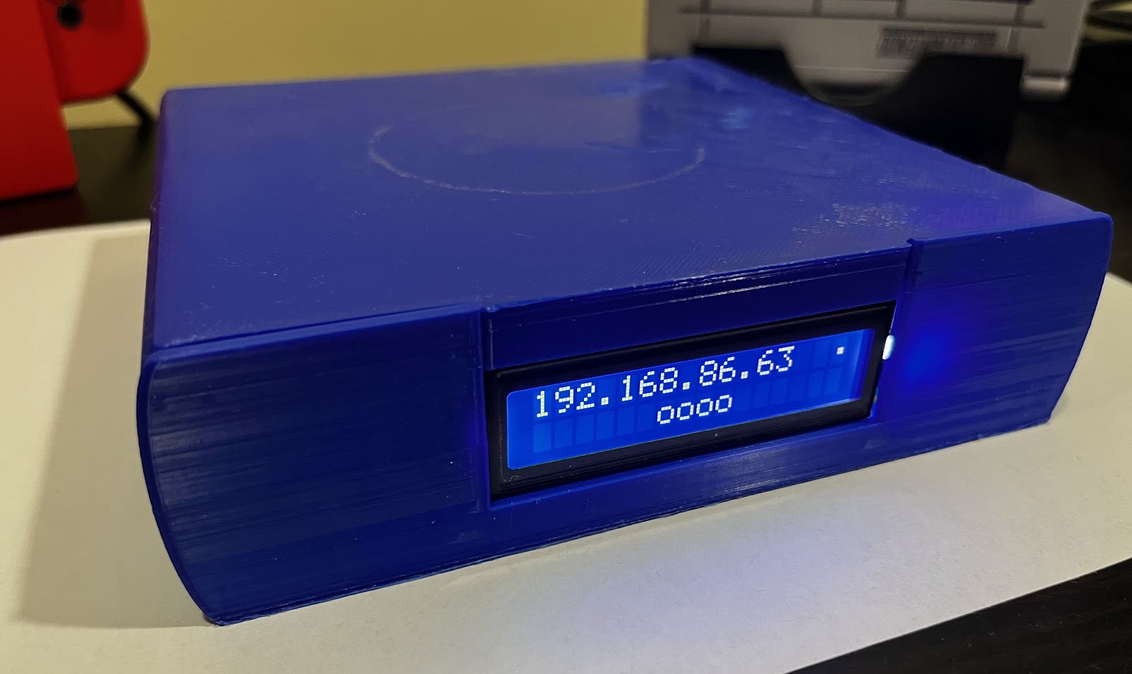
  • Front panel shows device IP and on/off tally icons for quick viewing of status

If you have a Spyder video processor of any generation, this device will work as a tally controller. For those wondering what tallies are, imagine a live show where multiple cameras are pointed at talent on a stage. Lights are usually physically positioned on top of the cameras and light up when a camera is ‘live’ to help the talent know which camera they should be looking at. The tally controller described here contains relays (electronically controlled contact closures) which open and close when specific sources are shown or hidden in windows on Spyder.

The video below walks through the device hardware and software, providing probably a better end-to-end overview than this blog post for those of us out there who prefer to consume video content.

Parts you Need

First off, you’re going to need to buy some parts. Here’s a list of what you need, some of which you may have around the house:

3D Printing a Chassis

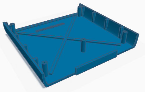
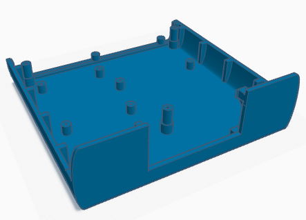
I used TinkerCad to design a simple chassis to hold a 4-relay board. You can copy and modify this design as you see fit, but for most folks you can simply download the 3D print STL files for the top and bottom pieces, and either print them yourself or send them off to a 3D printing service. If you watch the video from earlier in this blog post you’ll see the Raspberry Pi and the tally board are on the wrong sides of the chassis, and I’ve corrected this in the current design.

Chassis Top PieceChassis Bottom Piece
View in TinkerCadView in TinkerCad
3D Chassis Parts for Tally

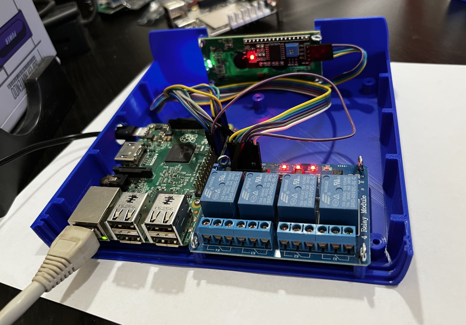
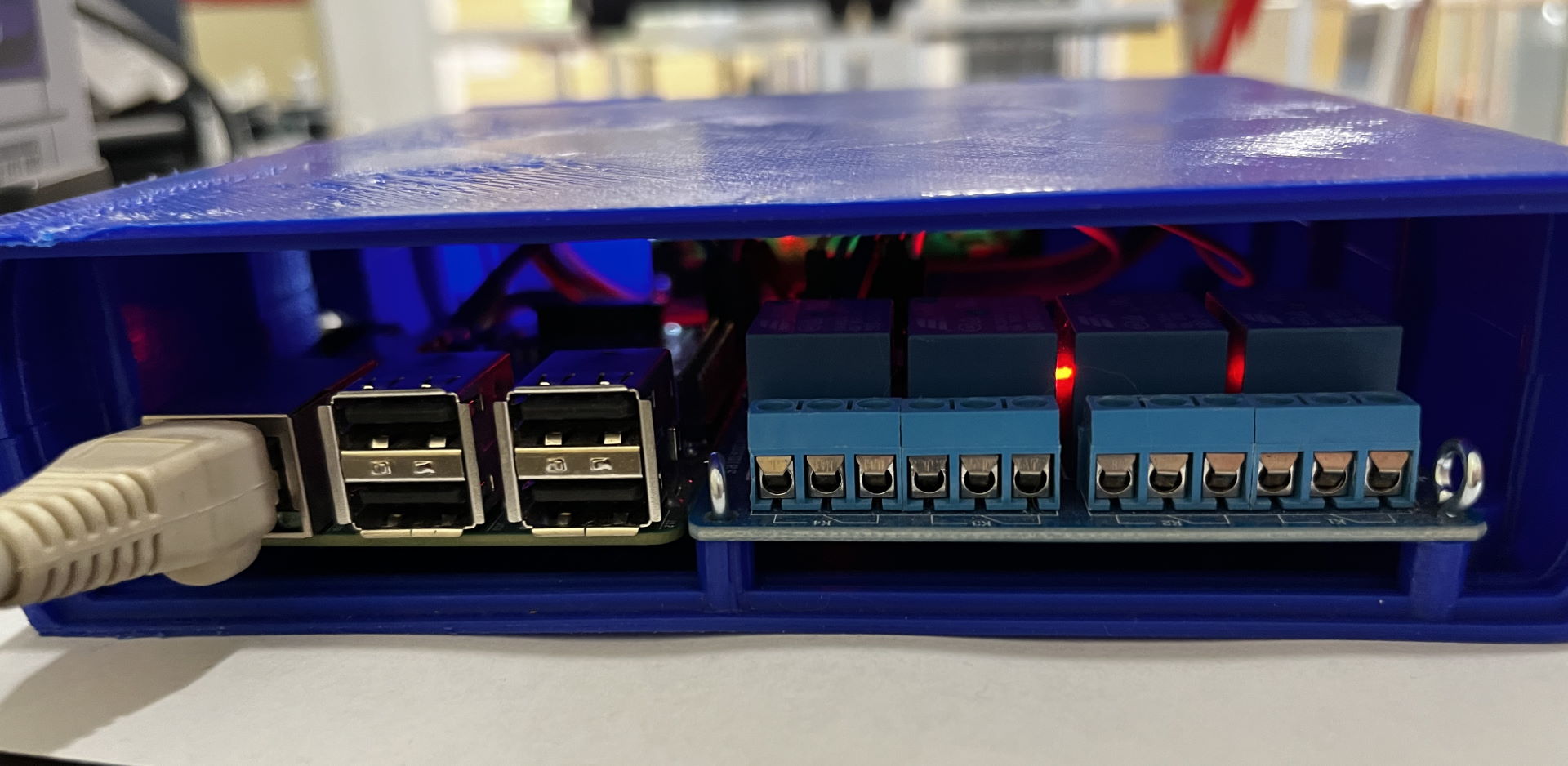
Building the unit is quite easy once you’ve acquired and printed the parts required. The open frame views in the video show off mounting the raspberry pi, tally board, and LCD front panel display in the chassis.

Wiring the pieces together

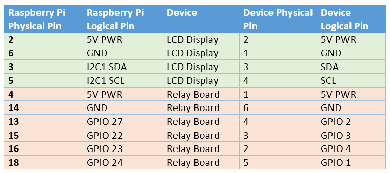
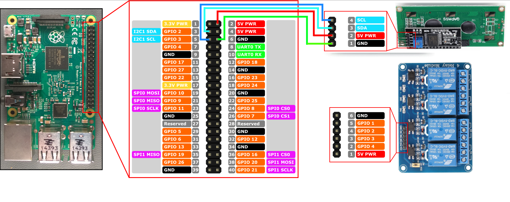
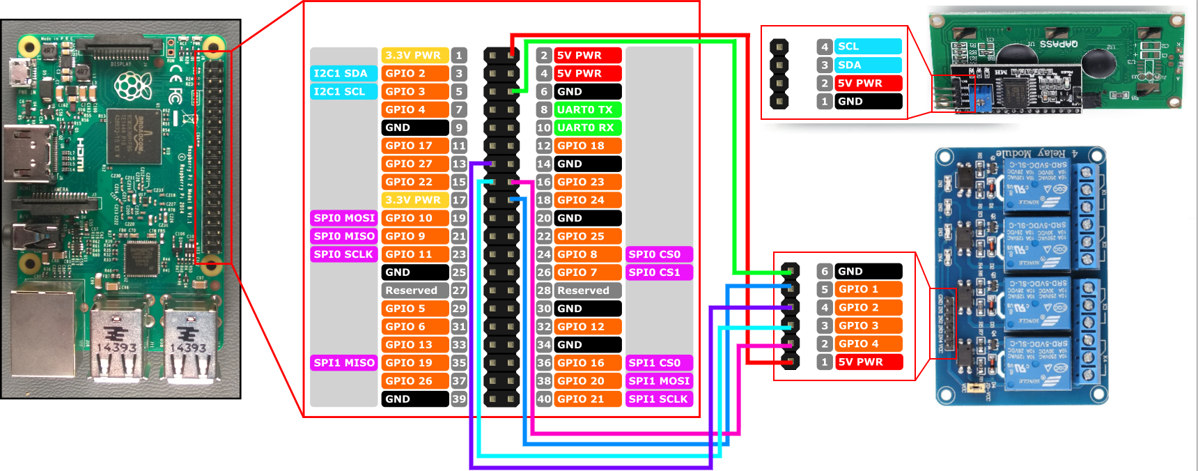
You can use simple breadboard style wiring connectors to save yourself from any kind of soldering, making the assembly a ‘Lego-like’ plug and play experience. The images below show the connections you’ll wire up from the Raspberry Pi to the LCD display and the relay board. If you’re creating a tally controller with more than the 4 relays shown, you’ll simply pick some more GPIO ports on the Pi for the additional connections (just be sure to write down which pins are connected to the relay pins for later configuration).

Spyder Tally wiring pinout
Wiring diagram for connecting Pi to the LCD display
Wiring diagram for connecting Pi to the Relay board

Installing the Pre-Built Raspberry Pi Software

Download SD Card Image for Raspberry Pi and/or release binaries here

Installing the pre-built software image for the Raspberry Pi is the easiest way to get going. You can download the SD card image directly from the Spyder Tally GitHub project’s releases page and use the official Raspberry Pi Imager tool to write that image file onto an SD card.

After writing the image file to the SD card, insert it into the Raspberry pi, connect an Ethernet (network) cable and power it up. It shouldn’t be necessary to connect a monitor to the Pi, but it does feel nice to keep an eye on it during the first boot where it will perform one-time tasks like expanding the file system to fill the SD card. That first boot will take several minutes, but eventually you should see the front panel light up and show the unit’s IP address.

Note that the software will wait for the network to become available before launching, and so you will not see anything until after the network is plugged in.

Installing Manually (Raspberry Pi or Other Devices)

If you’d like to use a device different than the Raspberry Pi, or if you want to build your own Raspberry Pi image for whatever reason, you’re in luck because it’s easy to do! The software may need some tweaking (particularly around hardware interface control) but should readily run on a wide variety of Linux devices including x86, x64, and ARM hardware with minimal tweaking.

The steps involved in creating your own disk image can be extrapolated from this README up on the project’s GitHub site.

One tweak I made when building the v1.0.0 SD card image – instead of installing the .Net Core framework on the device, I compiled the app as a ‘self-contained’ deployment. This kind of deployment bundles in all the .Net runtime pieces needed to run the application, and can both slim down the overall disk footprint and decouple the app from needing to be deployed on a target with a compatible .Net framework version. I like this approach and will likely continue this trend in future releases.

Summary

Spyder is an excellent product, and I’ve always been proud to have been a part of its history during my years at Vista / Christie Digital. Making accessory software and devices like this tablet controller still make me incredibly happy even years later. I hope you enjoy making your own as much as I enjoyed creating it. Let me know what cool environments you end up using it in!

If you run into any snags or have ideas for improvement on the project, the easiest way to communicate is to file issues up on the project’s official GitHub repository issue tracker. I do keep an eye out for comments and will try to reply as I can, but I tend to have a bad habit of not checking for comments for months at a time 🙂

ScreenMaster III 3216 – Restoring a Classic – Part 3

We’re going to keep the train moving in this post, and we’ll talk about taking the console interface software from the last post and connecting it to a message queue and finally to a new interface that will emulate the ‘Montage II’ console using by all variants of the Spyder video processor. By the end of this post, you’ll see a fully working console implementation. Better yet, project partitioning described here can be adapted to easily support different button board hardware, so stay tuned For those impatient like me, I’ve also put the final state demo video right below this sentence (you’re welcome).

First the obligatory high level picture of what we’re going to be walking through (below). On the console we’ve deployed three different applications running effectively as Windows Services. In reality the message queue writer and console emulator apps are running as scheduled tasks which launch on startup, purely due to it being easy to deploy, but they effectively are treated like automatically running services.

  1. ScreenMaster to Message Queue Writer: pushes hardware specific messages to a message Queue using standardized JSON messages
  2. RabbitMQ: Freeware message queue service maintained by a 3rd party
  3. Spyder Console Emulator: Translates messages between a message queue and a Spyder server. A Spyder server will think it’s talking to a ‘Montage II’ controller, which is the official console hardware platform for Spyder.

ScreenMaster to Message Queue Writer

Hardware interfaces come in all kinds of shapes and sizes, and in the case of the ScreenMaster III 3216 there is a hard-coded IP address scheme that makes it hard to develop and debug using a PC other than the built-in one. Other hardware interfaces, like on the ScreenMaster II 1608, use a serial connection inside the console between the hardware and the PC. Due to this, it became obvious early on that normalizing the specific hardware interface using standardized messages on a message queue would be a big help for development and debugging. Another positive outcome is that software can be written for any hardware interface, using any software language, and alas long as it implements the same standard JSON message structures it’ll ‘just work’ with the rest of the application stack.

The code repository for the message queue writer lives in GitHub here. As of this writing, the JSON message formats have not been documented, and so someone interested in making their own interface can look at the full set of classes in the messages folder for the existing project. The general messages from hardware to message queue include Key Action (press/release), Joystick Action, Rotary Action, and T-Bar action. Messages from message queue to hardware include setting lamp(s) on or off, and setting quick key LCDs (color and text). A key being pressed on the console, for instance, would generate a JSON message that looks something like this:

{
  "keyIndex": 102,
  "isPressed": true
}

The other message payloads are similarly simple. I encourage you to take a look at the GitHub project for details. It’s intentionally a small project, and should be easily replicated or adapted to work with other hardware consoles. Here’s a little demo using RabbitMQ’s built-in management interface to get and set messages to the ScreenMaster hardware.

RabbitMQ

I won’t spend a lot of time on this one, since it’s easily Googleable with Bing, but for those of you asking ‘What the hell is a Message Queue and why do I care’? The short version is that message queues allow multiple applications to send and receive messages between each other. There are several different implementations and vendors to chose from, but one (if not the) most popular offering is called RabbitMQ. I’ve installed RabbitMQ on my console, and it runs as a service in the background and launches when the internal computer boots. This works great for the message queue writer and Spyder emulator apps also running on the console, but it’s also REALLY great because I can connect to it from my desktop workstation for development and debugging. Before this I was actually slinging code directly on the console.

But wait a minute, you say, doesn’t putting a message queue between a hardware button board and some software processing create a noticeable degradation in performance? Short answer is no. Slightly longer answer (and in encourage you to look into it more if you’re interested) is that message queues are used as the backbone for enterprises and other environments like stock trading software that demand ultra low latency. There are some configuration options around delivery guarantees that can start to add up in some scenarios, but for our use case we won’t notice any performance impact.

Spyder Console Emulator

With the message queue in place, I have a bridge between a specific hardware interface and a generic messaging system. During that development, it occurred that it might make sense to make another application that would emulate a real Spyder console and translate between the message queue and the Spyder processor. It actually works quite well.

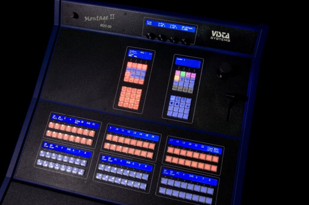
Quick (and relevant) history lesson. The ScreenMaster 3 (and subsequent Montage I console) drew a lot of criticism for having an embedded Windows computer. Other manufacturers (Barco comes to mind) took the opportunity to smear the product as being unreliable because of the internal PC. As a result, the Montage II debuted without any internal PC. The console is VERY simple – it has some simple menu capability to set a local IP and an IP for the upstream Spyder server, and listens for a handful of messages which set button lamps on/off (with an RGB color palette – see picture below) and set LCD text. It will also send network (UDP) messages to the Spyder when a button is pressed/released or if the joystick, rotary, or T-Bar position changes.

If you’re following along in the paragraph above, you may have noticed a couple things. First is that with the console effectively being a ‘dumb terminal’, the Spyder has to manage all of the console state and logic. Second thing is that the messages to and from the console follow a pattern quite similar to what I described earlier with the ScreenMaster to message queue application. Knowing these things, I decided to make one more translator; this time a translator between my message queue and the Spyder console interface.

To make this translation application, I need to do a few things:

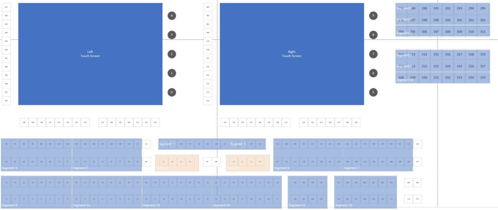
  1. Determine the button mappings used on Spyder’s Montage II consoles
  2. Define a mapping between buttons on the Montage II and my ScreenMaster console
  3. Write some software to emulate a Spyder console on the network so the Spyder hardware will actually think it’s talking to a console
  4. Make that software in the prior step interact with the message queue and translate messages back and forth.
  5. Add a key macro capability to the app which will ‘press’ the correct buttons to configure each of the segments of the console to ensure a desired state for the emulator.

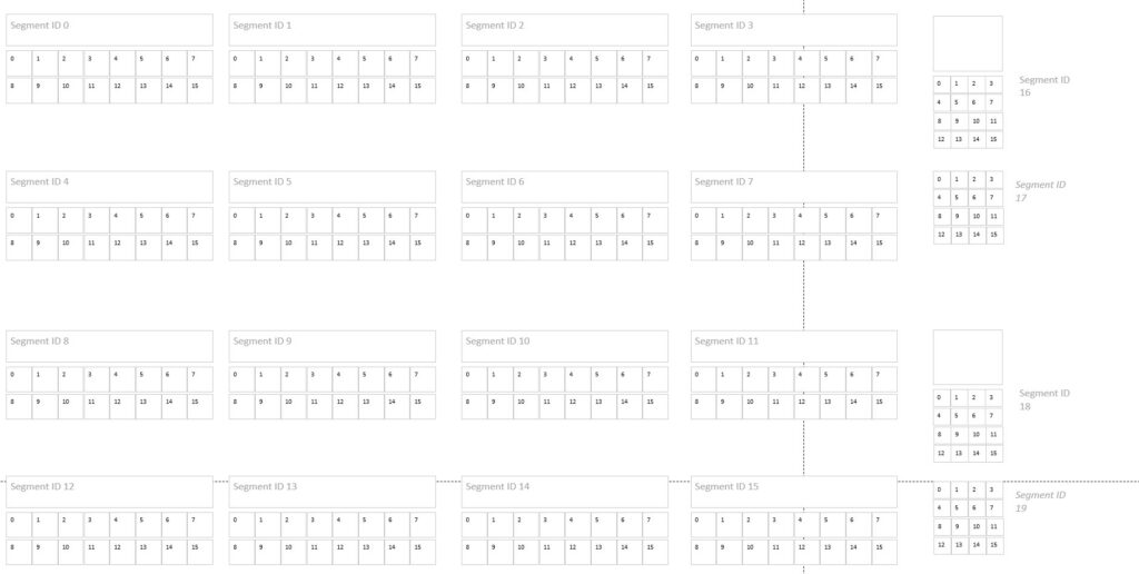
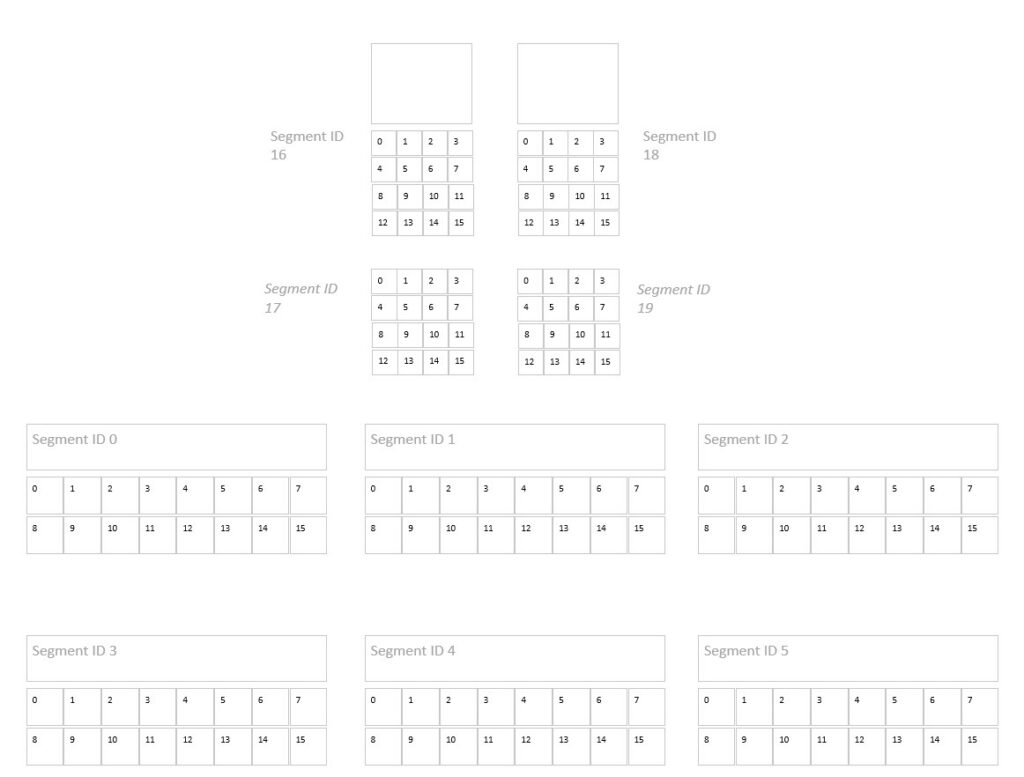
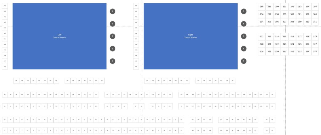
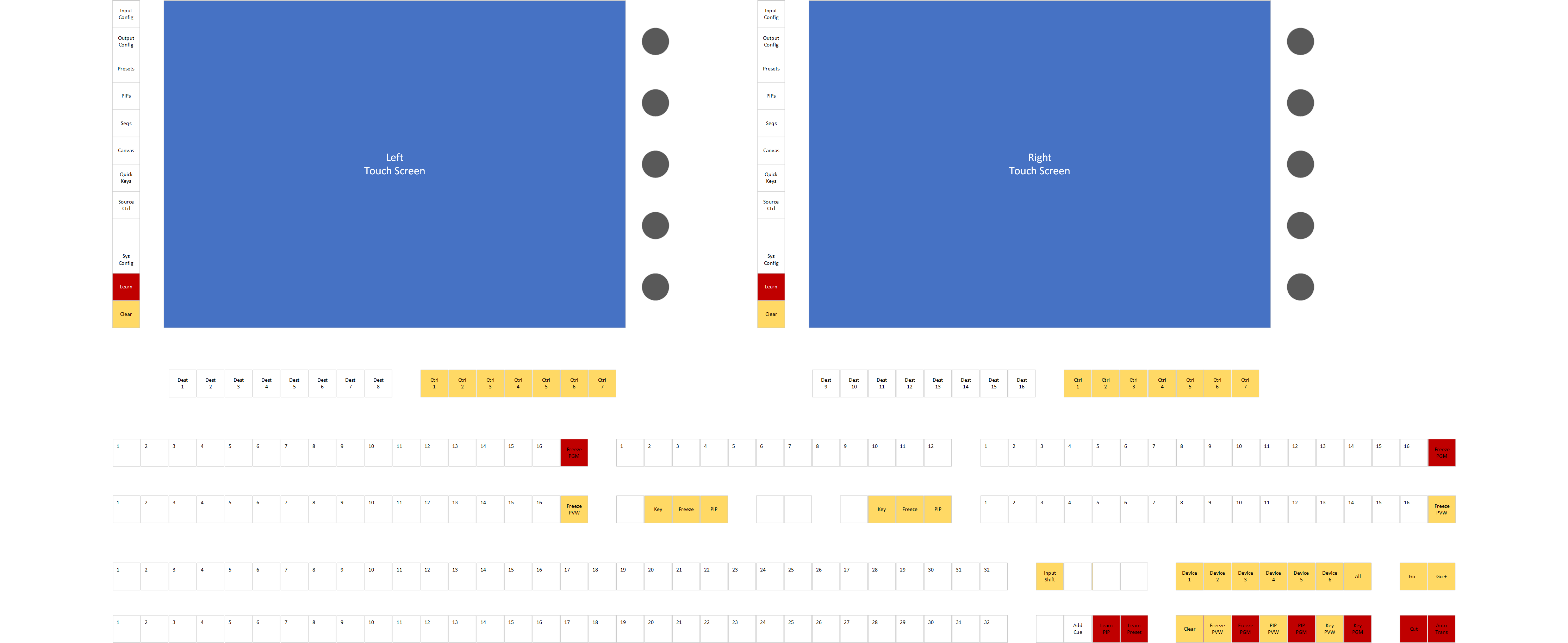
I created yet another Github repository for my ‘Spyder Translator’ with the code and relevant documentation. I created a Visio file with breakdowns of both the M2C-50 (smaller) and the M2C-100 (larger) console button assignments, and I also made a mapping of keys to my ScreenMaster console. Eventually this made it’s way into a JSON configuration file that I put into the repository, but a nice visual representation is always helpful for me. Some pictures from the Visio mapping doc below for reference:

The source code for the Spyder translator project in GitHub isn’t too crazy, and for those interested in looking further it offers a peek at a reference implementation for how the Spyder video processors communicate with networked controllers.

I’ll leave it to the reader to look further at the code repositories and refrain from turning this post into a code dump, but I’d love to hear from anyone who found it interesting or was able to build on it to incorporate some other cool hardware.

So Now Where are We?

At this point the ScreenMaster 3 3216 is an effective tool for controlling a Spyder video processor. The button mapping I’ve created has the quick key buttons mapped as Spyder Function keys, we have source selection and a full transition controller, command key and treatment control. Below is a walk-through video that I put up on YouTube to show off what the console is capable of. I was recording and trying to talk at the same time, so forgive me for the (low) production quality.

Now What’s Next?

The path I’ve gone down so far has been fruitful, but I very much would like to have some better and more native control of Spyder. There are some things I didn’t care for much with the Spyder controller, like only being able to access a single page of command keys or function keys, and not being able to create new items. This is due to the Spyder console never really getting much love – being a play-out device was generally just ‘good enough’.

All that said, I think it would be cool to make a ‘real’ control desk for Spyder, with full control of building things like treatments, command keys, and function keys. Deep integration of the screens to bring better selection context and more rich experiences would really make this thing shine. The timeline will likely come down to how much community interest exists, particularly now with the ability to relatively easily incorporate new and different hardware.

For now, thanks for reading and following along with my project. I hope it is able to tickle a few nostalgia bones out there, as it has for me. Until next time!
ScreenMaster III 3216 – Restoring a Classic – Part 2

In the first post in this series, we walked through upgrading the internal PC hardware within a ScreenMaster III 3216 hardware controller. In this post, we’re going to start creating the software to communicate between the internal computer and the hardware buttons, joystick, rotary encoders, and T-bar. All of the work discussed in this post lives in a GitHub repository that you can look through and use.

Before we dive in, let’s quickly agree on some terminology. I’m going to refer to the buttons, joystick, rotary encoders, and the T-bar collectively as the ‘keyboard’. Additionally, I’m going to refer to the Windows PC-based computer inside the console as the ‘host’. When we want to turn on or of a lamp for a button, for example, we’ll consider that to be a ‘host’ to ‘keyboard’ communication. Alternatively, when a user presses a key or moves the joystick a ‘keyboard’ to ‘host’ message will be generated. Hopefully this makes sense. Luckily the GitHub repository mentioned earlier in this post uses the same terminology in it’s documentation.

So how do we interact with the console hardware?

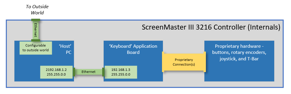
Communication between the host and keyboard is all performed using an internal Ethernet connection. This proved to be extremely helpful when upgrading the hardware, since we didn’t need esoteric connections to interface with the hardware. The keyboard has a hardcoded IP address of 192.168.1.3, and is hardcoded to send event messages to our host computer at the IP address of 192.168.1.2. This is quite limiting, but since it was initially designed to be an internal Ethernet connection we simply added a second USB network adapter during our PC upgrade dedicated to this interface. The image below shows the high-level Ethernet connectivity within the controller:

Over Ethernet, the messages between the host and keyboard are all simple UDP packets, with a very basic structure. I won’t detail the protocol here, but if you’re interested I’ve written up the protocol and published it within the GitHub repo here. Effectively, here’s the main list of things that you can do:

Host to Keyboard:
– Set lamp lights on or off for each button
– Set the LCD button background to Off, Red, Green, or some alternating combination
– Set the LCD button text – 3 lines, 6 characters per line

Keyboard to Host:
– Get event when button is pressed or released
– Get event when the joystick x, y, or z axis value changes
– Get event when a rotary encoder is turned (+/- change value)
– Get event when the T-Bar position changes

Time to write some software…

I’ve written and published a .Net Standard 2.0 library to implement the keyboard protocol and make it easy to consume from an application. The repository (listed at the beginning of this post) makes it simple to subscribe to events and control the simple pushbutton lights and LCD display buttons.

The repository contains a console test application that subscribes to events and writes these events to the console output. It’s a good example of how to use the library, and I’ve included a snippet of the test program’s Main function below for reference:

using Spyder.Controllers.ScreenMaster3;

static async Task Main(string[] args)
{
    // Initialize connection to keyboard
    var keyboard = new KeyboardInterface();
    await keyboard.StartupAsync();

    // Subscribe to events from the keyboard
    keyboard.TBarValueChanged += Keyboard_TBarValueChanged;
    keyboard.KeyPressed += Keyboard_KeyPressed;
    keyboard.KeyReleased += Keyboard_KeyReleased;
    keyboard.RotaryValueChanged += Keyboard_RotaryValueChanged;
    keyboard.JoystickValueChanged += Keyboard_JoystickValueChanged;
    keyboard.KeyAction += Keyboard_KeyAction;
    Console.WriteLine("Listening for events");

    Console.WriteLine("Press enter to exit");
    Console.ReadLine();

    Console.WriteLine("Shutting down...");
    await keyboard.ShutdownAsync(); 
}

If you’re playing along at home, you can pull down the library and build it from source, or for convenience I’ve also published it as a Nuget package for easier consumption.

Mapping out the buttons

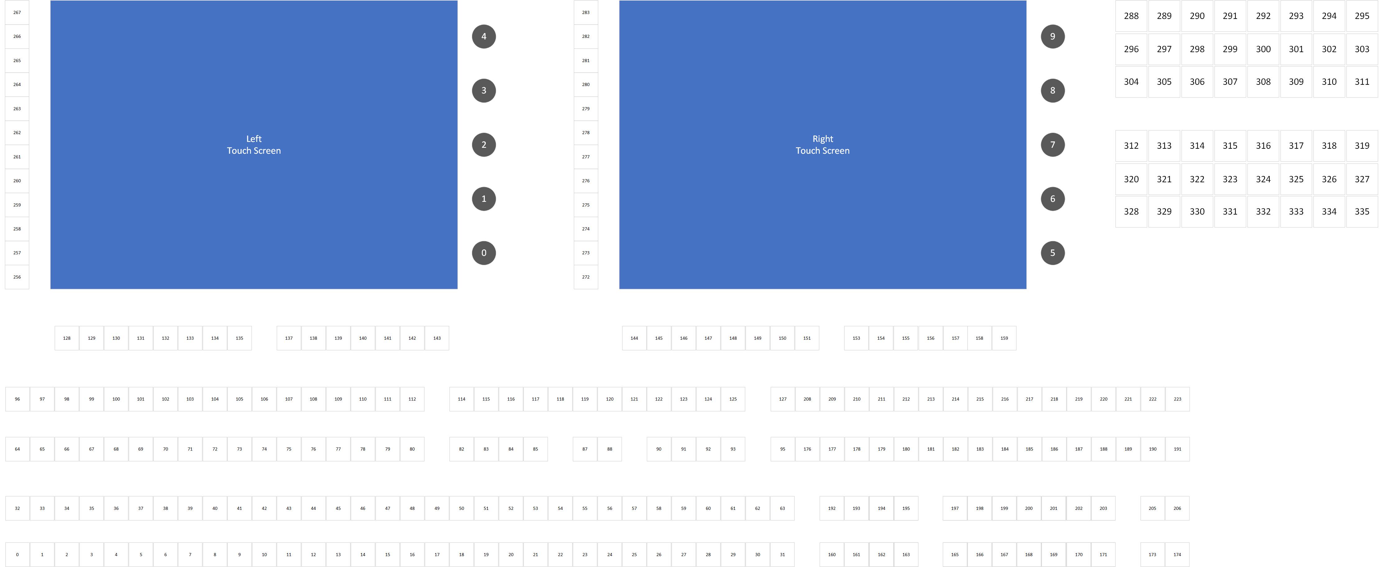
With a software driver library and a test application created, we can now go through the process of pressing and releasing every button on the controller, and watching the event data to determine the logical button ID associated with each physical button and rotary encoder. The console has well over 200 buttons, so it took a bit. My GitHub repo has a Visio document with some different pages that include the index map, and below is an image of this as well as a keycap map for the ScreenMaster III 3216.

Now where are we, and where do we go next?

At this point we have a controller with a modern computer inside, and we have a software library that allows us to interact with the hardware keyboard. With these in place, the real technical challenges are out of the way and we can focus on building an application to control something similarly modern. With my history and existing software libraries and software applications to control Spyder video processors, it’s probably not a spoiler alert to say this is where I’m heading.

I’m not sure yet if the next blog post will be software heavy (yet) – I’m planning to spend some time planning a good console application before diving too far into code. That being said, I couldn’t resist getting some simple app(s) started. As such, I’ll leave you with a quick video showing an app framework that works with the keyboard interface and is setting the selected page based from menu button presses.

If you’re still with me reading through this blog series, thanks! I don’t expect this project to amount to much more than a love letter to an old product that holds nostalgic value to me, but I hope it might resonate with a couple people out there. And if you’re lucky enough to have one of your own ScreenMaster III or a Montage controller lying around, let me know about it!

ScreenMaster III 3216 Console

ScreenMaster III 3216 – Restoring a Classic – Part 1

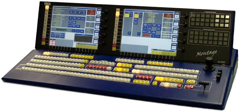
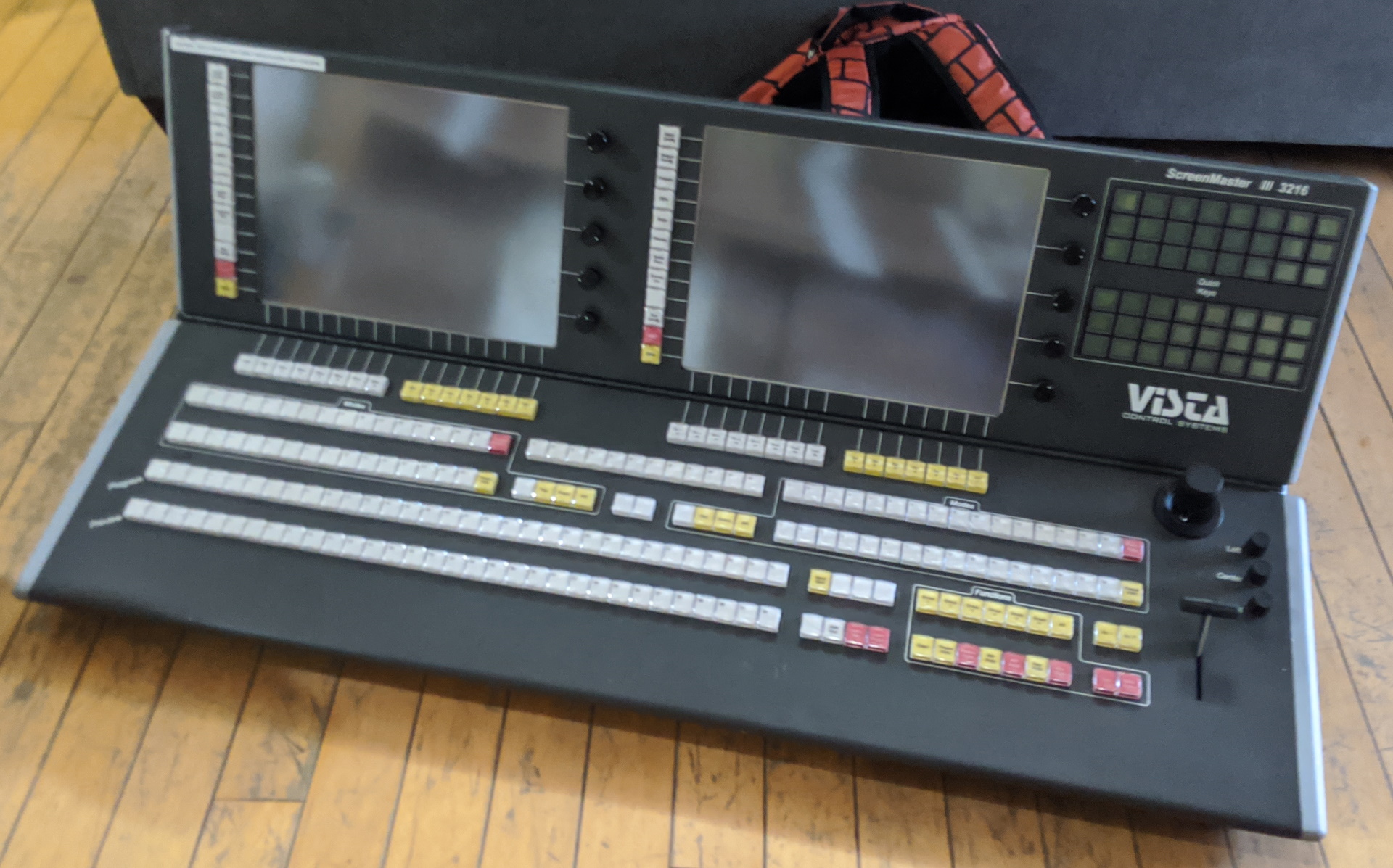
The ScreenMaster III 3216 and it’s half-sized little sibling the 1608 were some of my favorite consoles every made at Vista Control Systems (later renamed to Vista Systems and later acquired by Christie Digital). These were the first consoles to incorporate 15″ touch screen displays to compliment the massive button boards from prior console generations. This console, like others before it, were purpose built to control a combination of Folsom (now Barco) VFC-2200 scalers and either Extron, Pesa, or Sierra routing switchers. We’re talking analog video only here – this was the nineties after all, when 1080p video was king.

It’s worth a note that this console would be appear again in the future as the control surface for the Vista Montage video processor, painted in blue and re-dubbed as the Montage SC-3200 console. This stuff is all but lost in time, even on the internet these days, and so I’ve included a picture below for full historic reference.

Let’s talk about this got started

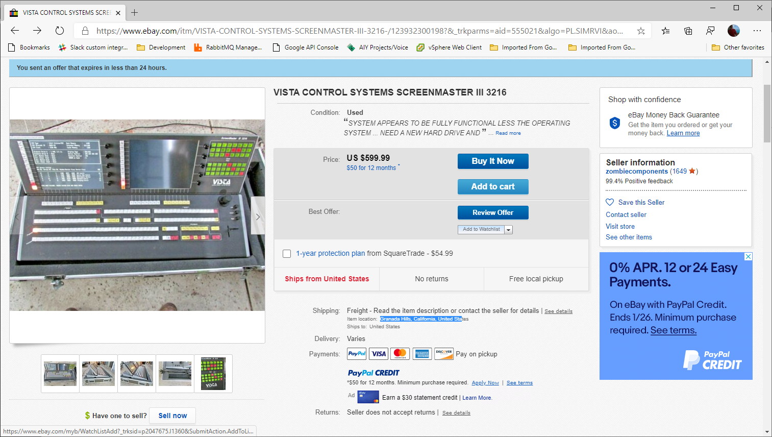
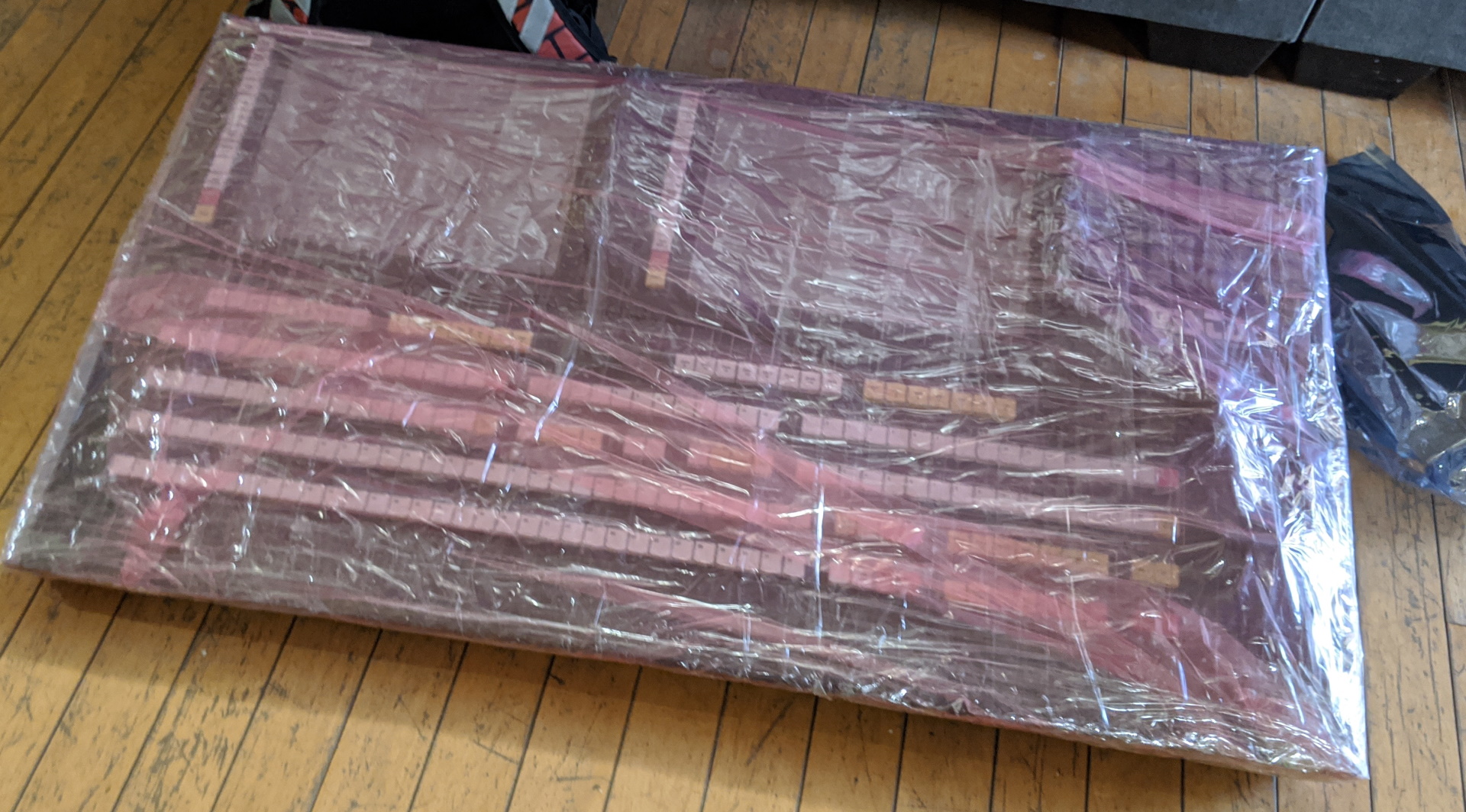
Let’s talk about eBay. eBay is a great place to get great deals, and is a great place to troll late nights when you can’t sleep to find stuff you didn’t know you needed (and probably don’t need). One night I happen to be aimlessly looking around the internet, and somehow I made it to this posting on eBay:

This picture of the console immediately gave me ‘the feels’, as it has solid sentimental value. I remember shipping the first of these consoles, sometime back in the nineties. We had a problem with a driver for an internal USB network adapter, and it was causing the console to bluescreen. We weren’t sure it was fixed, but I ‘thought’ I had resolved the issue with an updated driver. We got the console in it’s case and brought it to the back door. After talking a bit about this bluescreen, Jeff Wilson and I opened the console up and made sure it booted successfully five times. As long as it could boot five times in a row, then we’d ship it. Good news – that was the day unit #1 shipped.

<rant>Just to touch briefly on that last point – this was a time when Windows was considered to be generally unstable, and we caught a lot of flack from rental and staging customers (and competitors). Here we were though, shipping a device with Windows (NT Embedded I vaguely recall) and asking customers to entrust their high-dollar live events on it. Software bugs aside, I think this ask proved to be a reasonable one and these consoles were way ahead of their time (my opinion). </rant>

So this console on eBay had an asking price of $599, and I sent an offer for $299 which was accepted. I don’t remember the real figure, but I think this console cost around $45,000 new. From the pictures I could see some button-board activity and a boot failure, and so I knew that (1) the embedded part of the console was alive and (2) the PC was ‘alive’ and the Compact Flash card we used for the hard drive had likely failed. After some back-and-forth on the shipping, we decided to drop the shipping case to avoid going freight, and all-in I think I was down $500.

The arrival

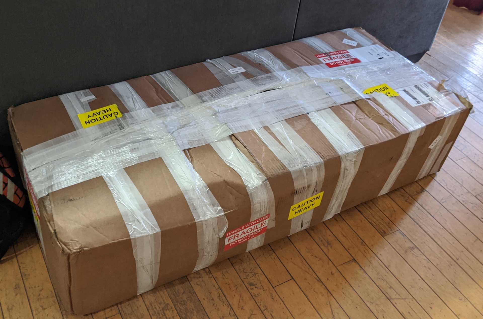
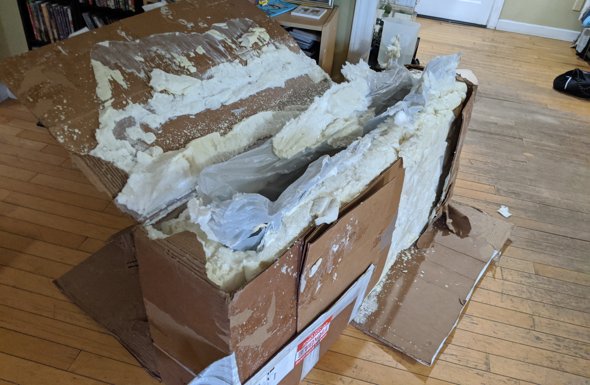
It took about a week for my console to arrive, and it showed up packed tight with instant-foam in a box that must have had a roll of fiber tape for additional support. It took a solid hour to practically chisel the console out of this foam tomb, but it shipped in pristine condition so I can’t complain.

After getting the console freed from it’s shipping cocoon, I gave it a good look over and powered it up. The screen showed the same hard drive failure message that I saw on the eBay post. The quick-keys (the top-right green button array) showed diagnostic counters that I was able to use to verify that the buttons, joystick, T-bar, and rotary encoders were all functional (minus a few burnt-out incandescent switch lamps). So far so good. Next up is to take inventory of the computer hardware and try to get it working again, but before we move on go ahead and take a hard look at that good-looking piece of hardware 🙂 .

Console internals

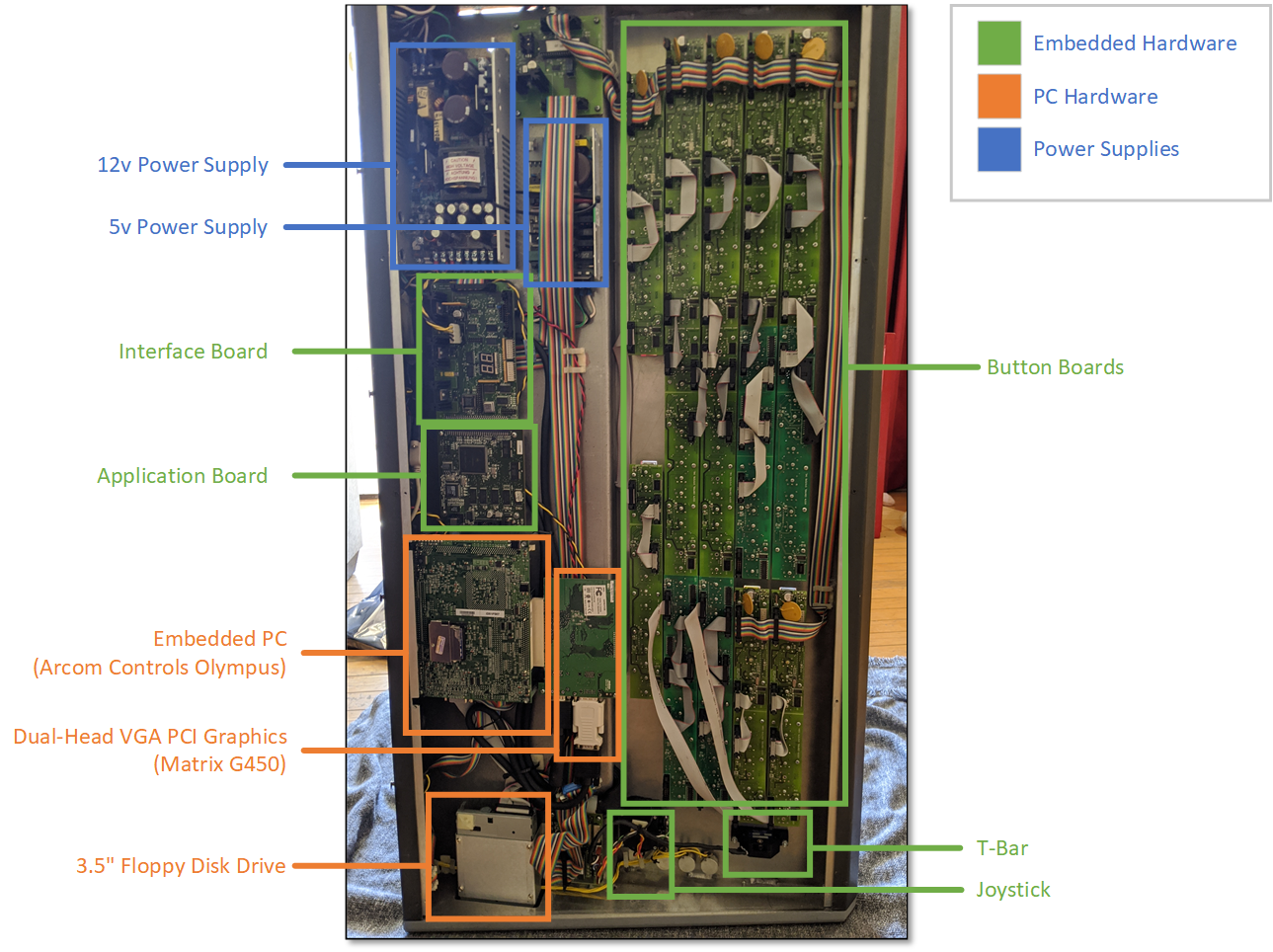
When you open the bottom of this console, you immediately see that there is a LOT going on. Luckily, when we look closely at the internals of the console there are two main subsystems – the embedded computer (PC) and the physical control interface (buttons / T-Bar / Joystick) subsystem. The picture below shows the console on it’s side with the bottom removed.

The application board is the main embedded component which houses the programming required to read and write the physical hardware. Luckily for us, the interface between the embedded computer and this application board is Ethernet. It’s difficult to see in the pictures, but there is an Ethernet crossover cable between a second Ethernet port on the SBC and the application board. This is great, because it means that we can upgrade the embedded computer without worrying about obscure hardware interface dependencies.

Before we move on to replacing the embedding computer, let’s take a second to talk about the embedded computer that came with the console. This was an EBX form factor computer called the ‘Olympus’ and was manufactured by Arcom Controls (datasheet here). This was a 1.0 Ghz Celeron processor and 128MB of RAM. The hard drive was provided with a 128MB Compact Flash card, which has limited read/write cycles and almost certainly explains why the console eventually stopped working. I did try jump-starting the console with a new Compact Flash module, but the SBC was so old that it felt that even if I could run a modern operating system on it (unlikely) that it would be terribly slow. It was also sporting a 3.5″ floppy disk drive, for those of you who remember what that even is, and I knew that needed to be brought into the modern age as well. With that back-story out of the way, let’s get to upgrading.

Upgrading the Embedded Computer Hardware

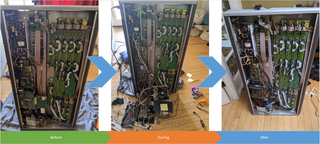
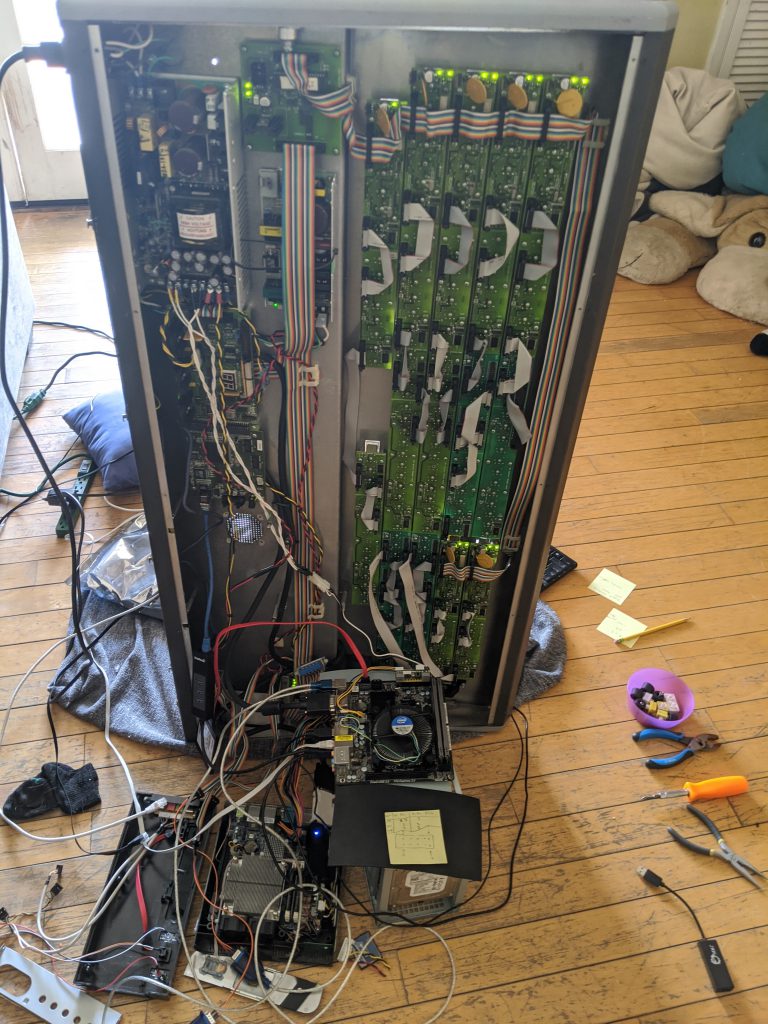
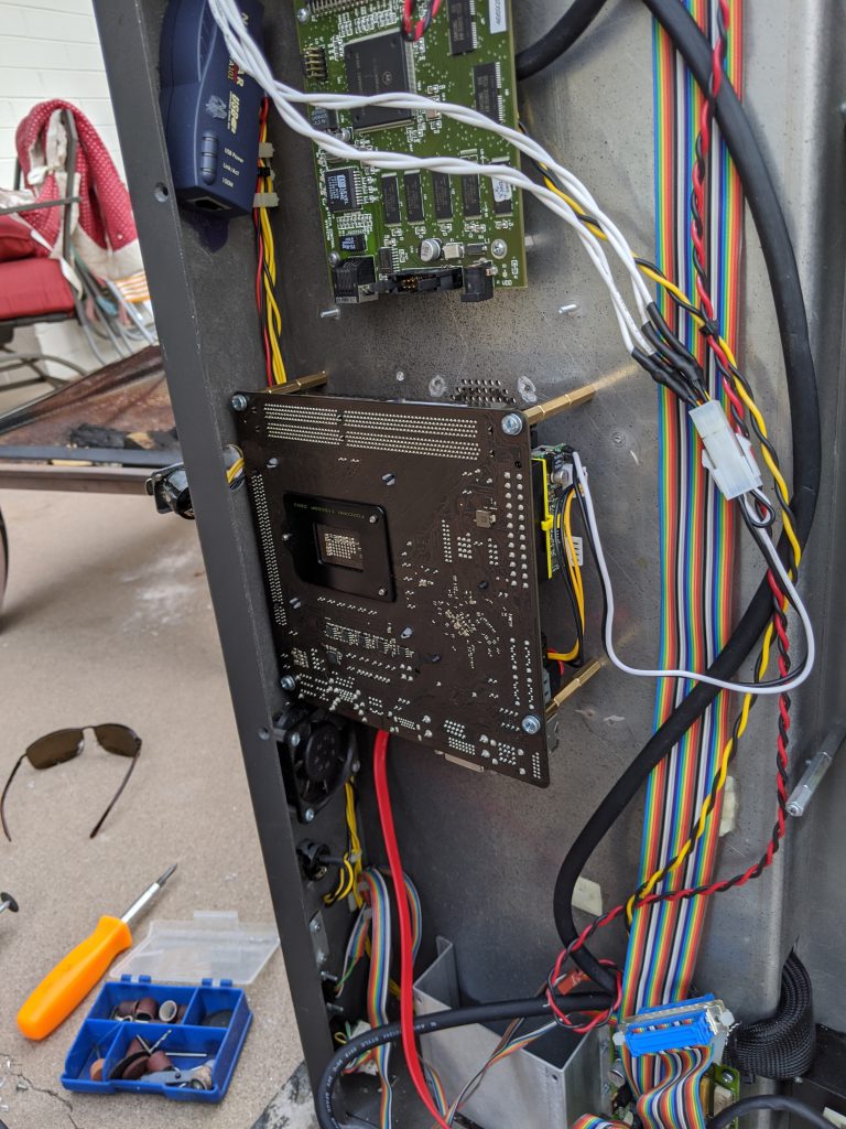
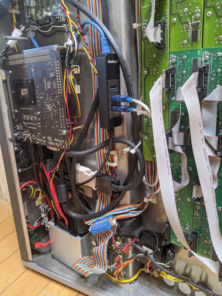
Full disclosure here – this console sat on it’s side in my living room for several weeks, and I’d give it occasional blocks of evening and weekend time. This wasn’t particularly hard, but there were some time-consuming parts of the effort that I’ll bullet point rather than writing a book about:

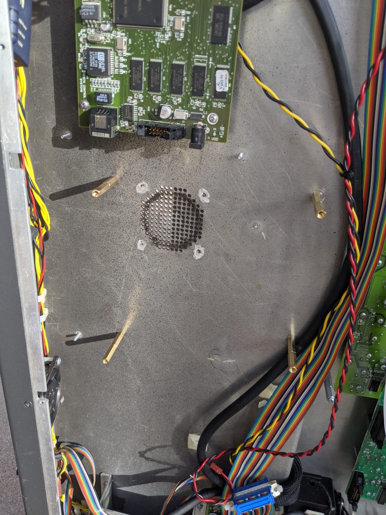
  • Removed the prior EBX form-factor PC board and graphics adapter
  • Removed the existing floppy disk drive
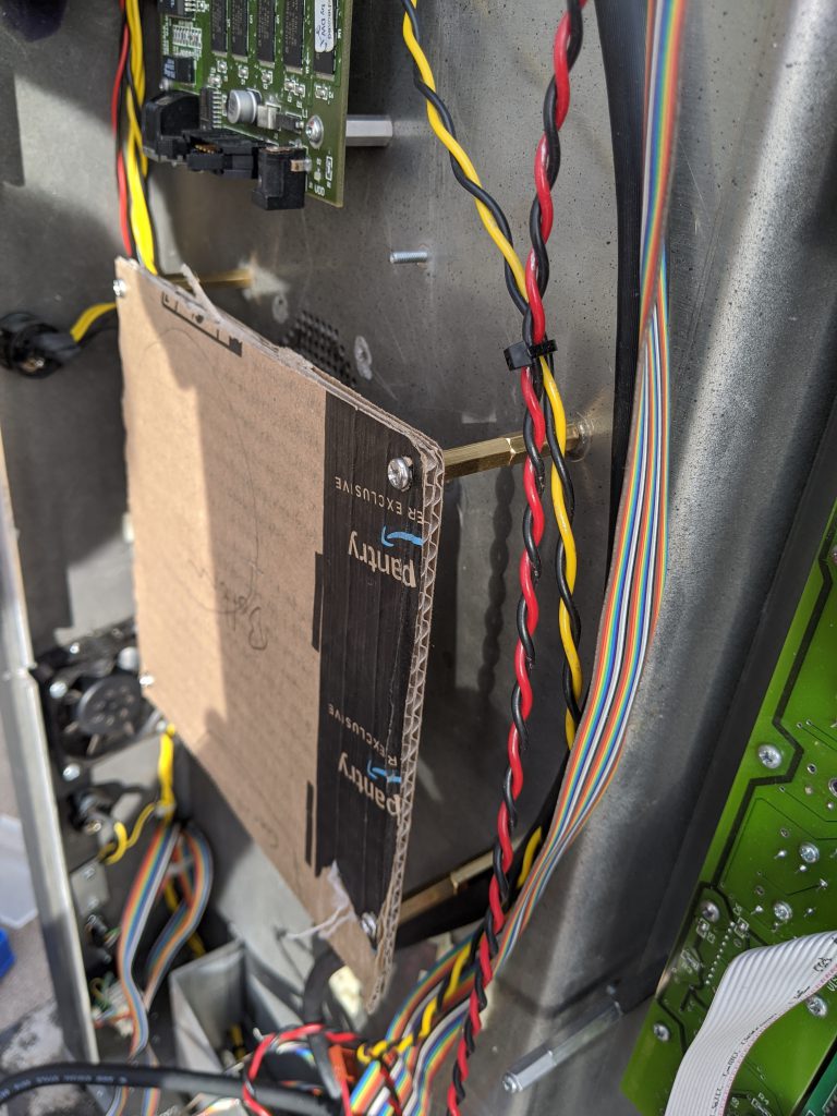
  • Drilled holes in the chassis to fit a new Mini-ITX form factor PC
  • Bought a +12V to ATX power adapter module to power the new SBC
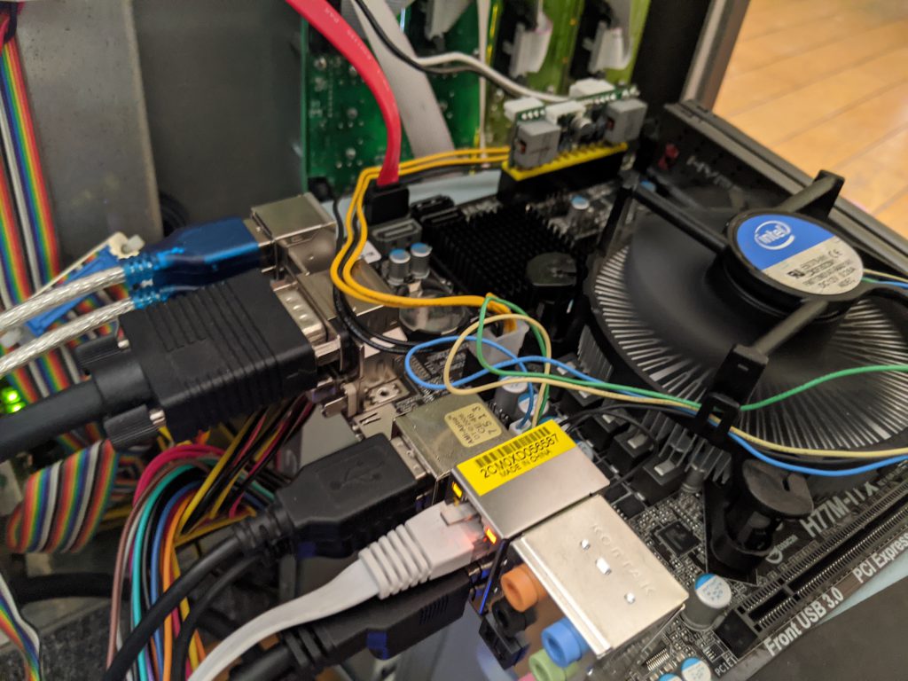
  • Added two USB to RS-232 cables to drive the touch screens
  • Added a USB to Analog adapter to drive the second touch screen (the SBC had one VGA port I was able to use as well)
  • Replaced the Neutrik Ethernet connector running to the back of the console with a new one
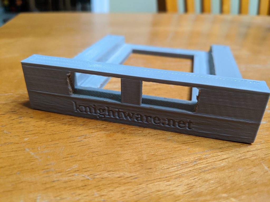
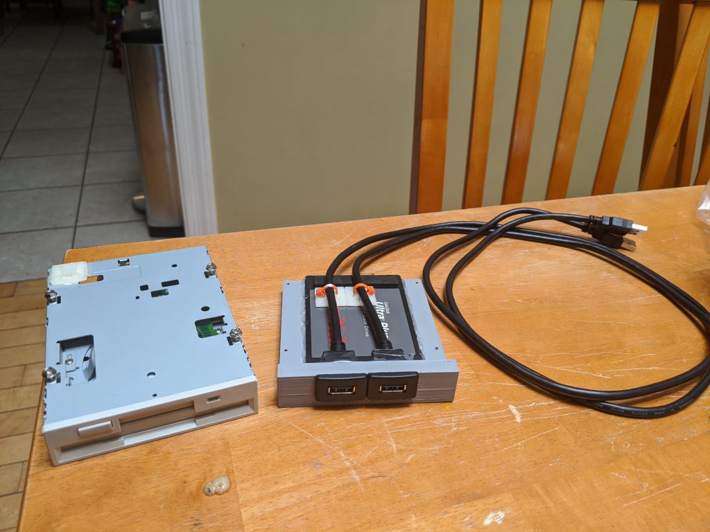
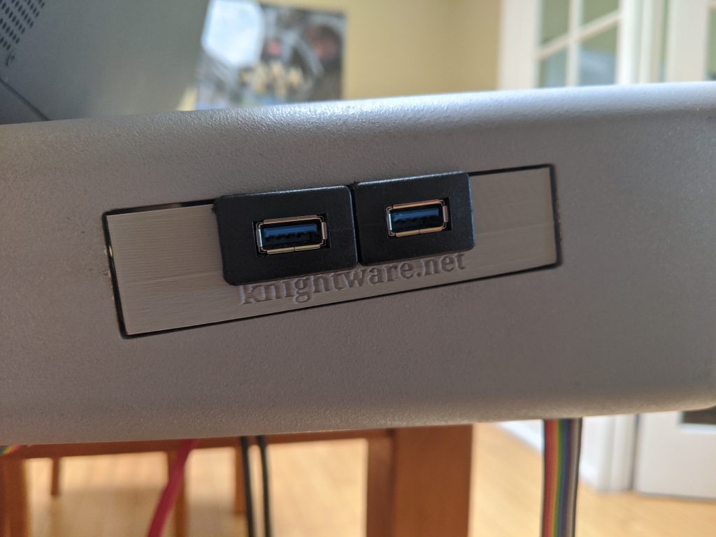
  • Modeled and 3D Printed a custom bracket to hold a new Solid State hard disk and expose 2x USB 3.0 ports to fit in the old floppy disk drive spot.

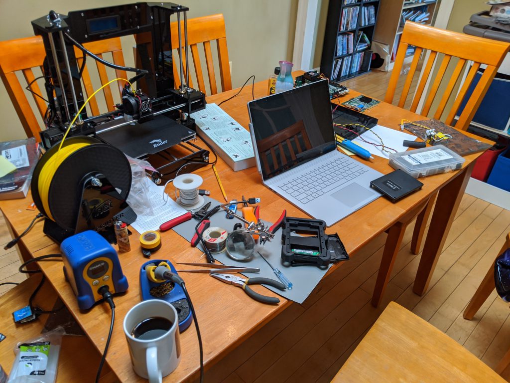
The mounting and retro-fitting of the new SBC and parts was a pain, but I’m pretty happy with how it came out. This thing feels like it could travel and be as reliable as the original console was. I am particularly proud of the 3D printed module that I made to hold the hard drive and expose a couple USB ports, and you can see this along with a bunch of other build pictures below

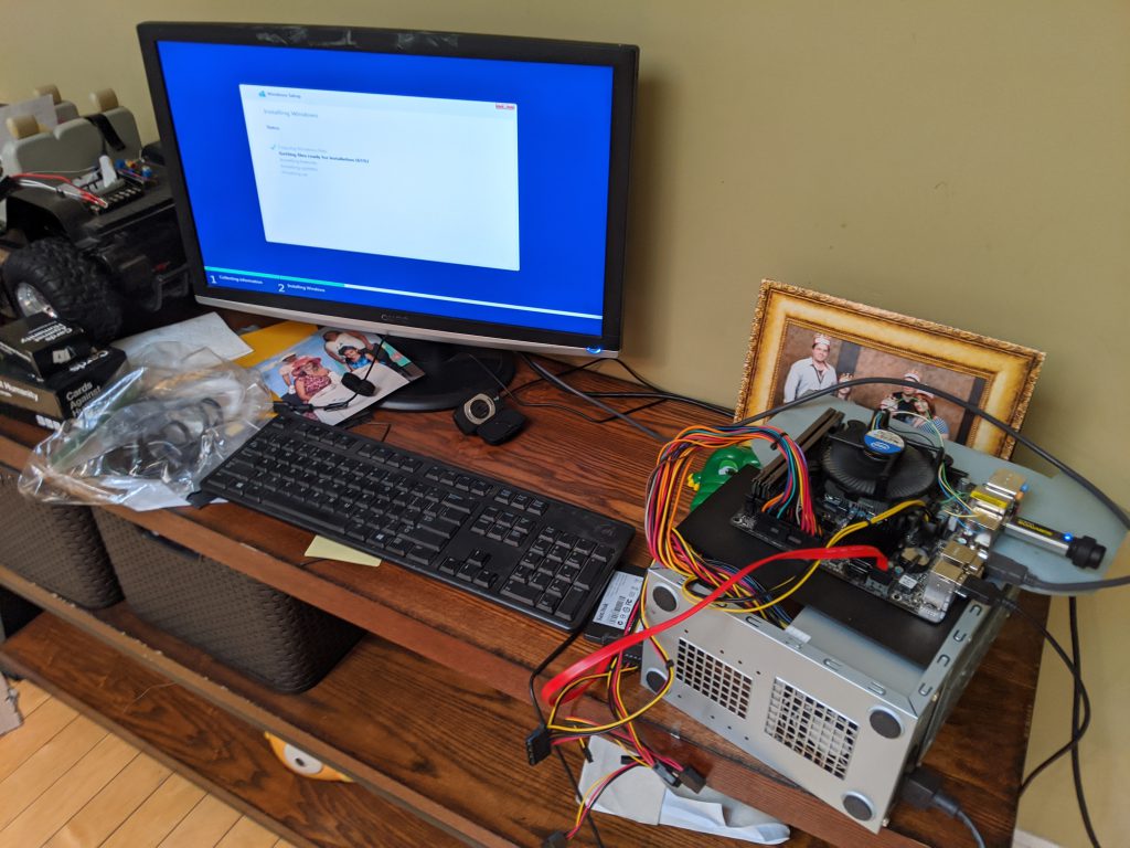
After the aforementioned evenings and weekends spanning may weeks, the hardware for the console was done. It was now sporting an Intel i7 processor with 16GB RAM and a 512GB solid state disk, and was running quite nicely. I did sneak in a picture of installing Windows on the replacement Embedded PC / Single Board Computer (SBC), but I’ve saved this for the last section of this post.

Let’s put Windows 10 on this thing

A modern console needs a modern operating system. I actually considered installing Ubuntu Linux for the fun factor, however ultimately I decided to install Windows 10 Pro. It’s less ’embedded’, but it allows for wider flexibility for software to run (including Vista Advanced / Spyder Studio / Spyder Client software).

One wrinkle that I did run into was around the touch screens. They have RS-232 serial controllers, and the native 3M driver didn’t work. I remember running into this with my Car computer touch screen (same hardware), and so I knew I needed to pony up and buy a license for a software called touch-base that makes the touch controllers work with Windows 10. Related note – the screens for the console are each 1024×768 resolution and VGA, and if I were braver I would crack open the top and try to replace them with some newer displays. Maybe someday.

Big reveal time

I don’t need a lot of words for this – I’ll let the pictures of the console working speak for themselves. For those curious, the pretty looking Spyder control software is the Spyder Client application that is available on the Windows 8/10 Store.

So where are we, and what’s next?

So we have a large powerful hardware console alive and well, and we have a working PC operating system on it. Probably a way over-powered PC in there hardware spec-wise, but we still don’t know what we’ll do with it so hard to say. By the time I write this, the console has actually been sitting in my dining room for the past two months. I’ve already done some development and created a software interface to integrate the hardware with the PC, but I’ll save that for a future blog post.

In the next post, I’ll talk about how the PC-to-embedded hardware interface works, and we’ll probably have a simple app to show take a look at. I expect the next post will be a bit shorter – this one was a monster and it feels like it just skims the surface. With that, thank you for reading and see you next time!

Using NPM packages from RunSmart microservices

The RunSmart workflow environment uses node.js for it’s microservice system, and in addition to the built-in libraries it’s possible to install and use Node Package Manager (NPM) packages. This is incredibly handy, and this post briefly shows how to install these packages and consume them from RunSmart workflow scripts.

Note: It is of course possible pull down the code for npm modules and maintain native RunSmart libraries, and gives tighter control of the code running on your system. In practice however, this becomes a large task with anything than non-trivial npm packages due to the number of package references they tend to use.

Installing NPM Packages

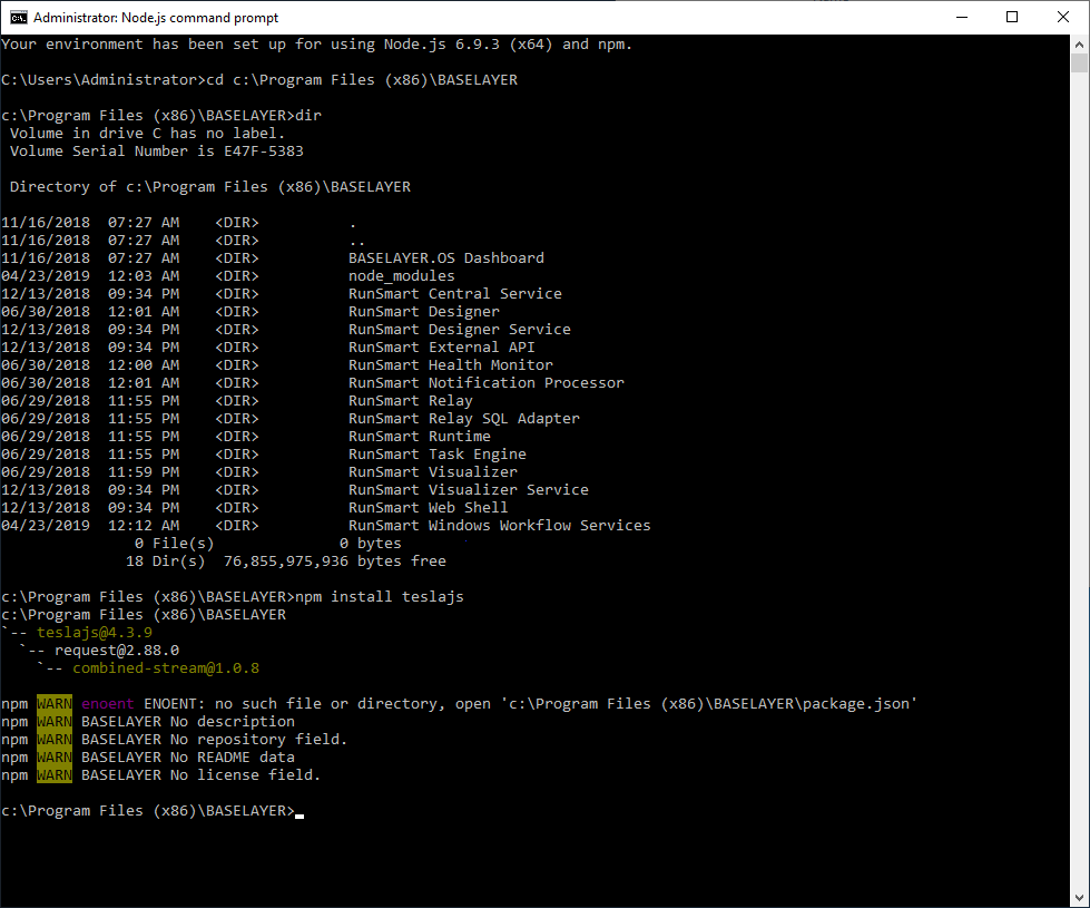
To install npm packages, you’ll need to remote onto the server hosting your Windows Workflow Services installation. From this computer, open a node.js command prompt, and navigate to your installation directory for RunSmart (usually c:\Program Files (x86)\BASELAYER). This is the directory that will be used as the search path for node_modules, and if you look at the contents of this directory you may already have this directory present. If you don’t, no worries as it’ll be created when you install your first package.

To install a package, you can usually just run npm install <package name>. In the screenshot below I’m installing the TeslaJS package, which I use for monitoring my car.

Installing an NPM package to be consumed by RunSmart Workflow microservices

Using NPM Packages in your RunSmart Microservices

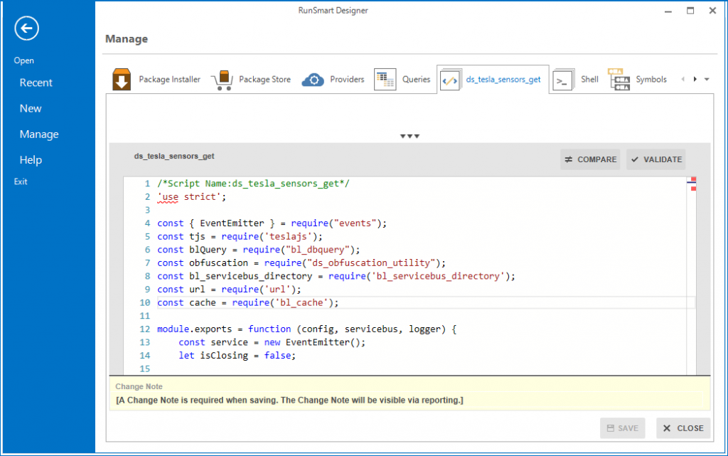
From your RunSmart microservice scripts, you can use the normal node.js require statement to bring in your libraries. The library loader will first look for a local (in database) script matching the require statement, and will afterwards search the node_modules directory.

Importing the npm module ‘teslajs’ (line 5 of the microservice script)

That’s all there is to it!

The great garage refresh of 2018

In December I pulled the trigger and ordered a new Tesla Model X. Being more of a computer on wheels than a car with a cool computer and autopilot system, this car speaks to me on a level deeper than I can comprehend. The time from order to delivery was a little over three months, and it became apparent immediately that it would need a worth garage to call it’s home. This blog post is a chronicle of the creation of just such a garage.

Where we Started

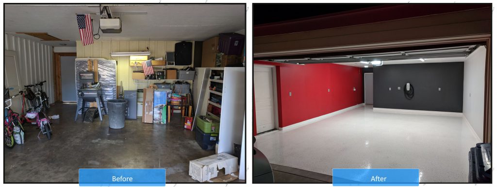
The garage had years worth of stuff packed into every corner, and hadn’t seen a car actually parked in it for quite some time. I wouldn’t allow my shiny new car to bake in the driveway, so initially it seemed obvious that a clean-out and maybe some paint on the walls and cabinets was in order.

First Attempt

At first all I really wanted to do was paint the walls and cabinets, and clean up the junk that I had accumulated over the years. As the space cleared out and I went to painting, I started noticing how the cabinets weren’t really in great shape, and were starting to crumble. I went to painting anyway, but realized quickly that there wasn’t going to be much of an improvement. I got through a couple walls, but didn’t even get to painting the cabinets. I knew this was going to become a much bigger project…

Tearing it all Down

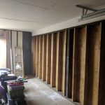
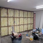
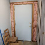
The cabinets were garbage. I ripped out all the cabinetry, and then was faced with bare studs that would need some drywall. The garage had previously been a carport, and so the walls it did have were exterior walls or just bare studs. These exterior walls were 1/2″ wood with slats, and I finally broke down and ripped all that out as well. The covering of the uneven wall along the house came out and revealed a door and a window that had been covered over on the other side during a previous remodel. One wall after another, I kept tearing more and more down until I had pulled almost all walls, with the exception of half the wall running along the house, down to the studs.

Adding more Power

While the studs were exposed, I added electrical outlets to the outside and back walls, and ran the power line up to the attic. I also added a pair of 8′ LED strip lights which look like fluorescent fixtures to give the room a brilliant white light. This lighting alone was a major improvement both for working in the garage as well as the finished product.

I had an electrician come in to wire up the outlets to a new 20-Amp breaker, as well as wire a new circuit to an 80-Amp Tesla wall charger unit which would live on the back wall of the garage. We had a few surprises – my electrical box is 3-phase, wasn’t grounded, and needed some work to fit some new breakers. We got through it in a few days, but between the Tesla wall charger, parts, and labor the whole endeavor set me back just over $2,000.

Building it Back Up

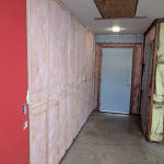
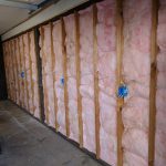
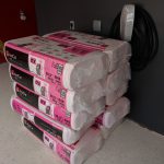
I framed out the half of the previously uneven wall against the house. The garage is notoriously an oven in the summer, so I decided to insulate all the walls and the attic while I had the opportunity. The ceilings are 8′ high, so I initially put in drywall strips vertically (they come 8′ x 4′). About the time I finished I found out that I should be putting a 1/2″ gap between the floor and the drywall, and also using special ‘green board’ drywall which is treated to resist moisture. I ripped all my hard work out and started again with new green board. There were some ceiling gaps that I fixed up along the back wall due to the prior 1/2″ wood boards being thicker than my new 1/4″ drywall.

To mud and tape the drywall together, I hired a professional. That is an art in itself, and I figured for all my work I wouldn’t want to do a bad job here and not get the benefit of clean/smooth walls. Had him mud the entire ceiling while he was in there, to get rid of the prior texture and some other holes and cracks that needed to go. $950 later I had something starting to resemble a legitimate garage again.

Finishing the Job

Painting the walls was easy, but painting the ceiling was much more difficult than expected. I stayed up many nights until 2AM just painting, and the excitement as it started to look like a showroom fueled me to push hard. With the walls painted, the floor became an instant eye-sore. It quickly became apparent I was going to need to go all the way and epoxy the floor. The idea of a showroom look had taken hold, so I committed to going with a white color.

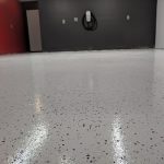
The prep work and application of the epoxy floor took as much time as the walls. I ground down the floors with a large grinder rented from the Home Depot. I ground down along the walls by hand using a hand grinder. Then I acid washed the entire garage to prep the concrete. Then I spent hours sealing cracks in the concrete to ensure a smooth surface. This process alone spanned weeks and cost a couple hundred dollars. The actual epoxy (two coats) and associated sealer/hardener (also two coats) cost around $600 and also spanned over a week due to curing time between coats.

The very final step was trim, which I waited several weeks before knocking out. Simple white, pre-primed trim pieces went up in an afternoon, and after a quick bead of silicon caulking I was finally done.

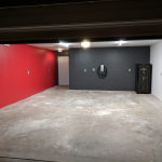
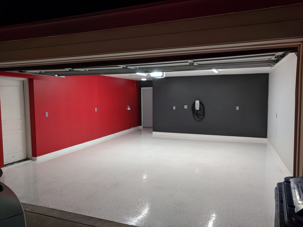
Completed Garage Renovation

Overall Thoughts Now that it’s done

At the outset if you told me I would spend over $5,000 to renovate my garage, I likely wouldn’t have started at all. But that’s not how great projects work. This garage is awesome, and makes me happy. Sometimes I go out to my car, stop, and pull out my phone to take a picture or two. It looks walking into a showroom every day. It’s worth it, and I hope for everyone to have something that brings them recurring joy like this. It’s a prefect compliment to the car, which also brings me boundless joy.

For those wondering or hating on the white floor – I mop it once a week and it looks brand new again after three months. The car doesn’t drip random oil or other fluids on the ground, so at worst you end up with some tire tracks after a few days. If you live somewhere rainy, your mileage may vary. In Phoenix Arizona it’s not bad.

Future Stuff

I would very much like to install three of the Tesla PowerWalls and some solar. Beyond the energy benefits, the visual design of those PowerWalls would really look amazing along that red wall in the garage.

I need to build a home for my bike, which is now living in the back yard. It’s covered, but it’s also an expensive machine that shouldn’t be left outside.  I already have some plans for this – look for that in another post soon.

Building a Camera Tally Controller for Spyder

Over this past weekend I set out to create a camera tally device for the Spyder video processor.  Specifically, I wanted to try to use my relatively new Raspberry Pi 2 board running the Windows 10 IoT Core operating system to make something useful.  If you’ve read through my older blog posts, you’ve likely noticed that the Spyder is still my go-to target platform for playing with new technologies.  Let’s face it – when you’re playing with shiny new toys, it helps to mate it up with something you know very well so you don’t feel completely lost.  Before I get into the details, check out this brief video showing a working tally controller in action:

The whole process of building this device was simply fantastic.  The barrier to entry for people making hardware devices has gotten incredibly low over the past couple years, both from a cost and ease of development perspective.  The whole build process was very quick, and I had such a great time with it that I went ahead and put together a full 30 minute hardware and software video walk-thru for the project (more on this below).

Getting Started Making your own

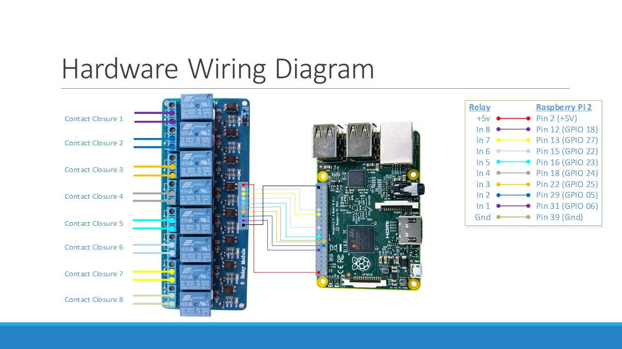
To get started making your own, here are a couple links for the main hardware used on this project, as well as the wiring diagram for your reference.

Raspberry Pi 2 Kit ($70):  Amazon Link
8-Channel Relay Board ($9):  Amazon Link

Tally Wiring Diagram

Hardware Wiring Diagram for our Tally Controller

Links to the full source code, documentation resources, and a full YouTube walk-thru video are below.  This video has a ton of valuable information in there, covering the hardware specifics, Spyder implementation details, and the full process of creating our software application.  This is the first time I’ve gone through and made something this elaborate (and narrated the video), and I’ll be very interested to know what you think of it (so leave me a comment below if you’re so inclined).

GitHub Project (Source Code and Documentation):  Click Here

Next Steps

The tally controller we’ve created is certainly functional. but in it’s initial form the server IP address and tally source lists are hard-coded.  In the next stage of this project, we’re going to build a desktop application that can connect to the device remotely over the network and view/configure these properties.  We’ll also explore creating a user interface to run on the Pi’s HDMI output, which could be useful for monitoring and troubleshooting the device.

Until next time, take a look through those walk-thru video and the resources in the Github repository, and try to make one yourself.  I hope you enjoy going through this content as much as I enjoyed making it.

Garage Door Opener Project: Part 1

So a few weekends ago I decided that I’d like to embark on a fun project of making a network enabled garage door opener.  A few weeks ago I was walking home from a neighbors, and found myself wishing I could open the garage from my phone, or ideally from my Band.  This seemed like enough of a pretense to embark on a new project, and after a few weeks of tinkering I’ve emerged with the following working home accessory:

The Plan

When I started this project, I laid out a few key requirements:

  1. Build an application targeting an existing Wi-Fi enabled Raspberry Pi I had laying around.
  2. Build and debug the application on the Pi, and write it in modern C++.
  3. Setup Git on the Pi, and keep the code up in GitHub.
  4. Breadboard the hardware required to switch the garage light and door.
  5. Integrate a temperature/humidity sensor to allow me to play with garage cooling options over the upcoming summer months.
  6. Add a garage door closure sensor so the device can tell when the door is open or closed, so the app can provide open/closed status back to network clients.
  7. Integrate my X10 Firecracker dongle, to allow me to control my existing X10 outlets/lights

The C++ requirement came partly from a desire to tackle a ‘real’ project with the language using modern language features like smart pointers, and to try out some of the Boost library’s programming constructs for asynchronous networking.  I’ve also been playing around with building basic electronic circuits, and making some necessary hardware for the Pi seemed like a fun time.

The Hardware

It took a while to get the electronics working, and I learned a decent amount along the way (even though there really isn’t much to this).  I started trying to trigger my 3.3v relays directly using the GPIO pins on the Pi, and when that didn’t work I had to go back and figure out that GPIO pins can’t drive the level of current required.  I was also using a shift register initially to reduce the number of pins coming off of the Pi, but it ended up being unnecessary and was eventually removed.

Testing first iteration using shift registers


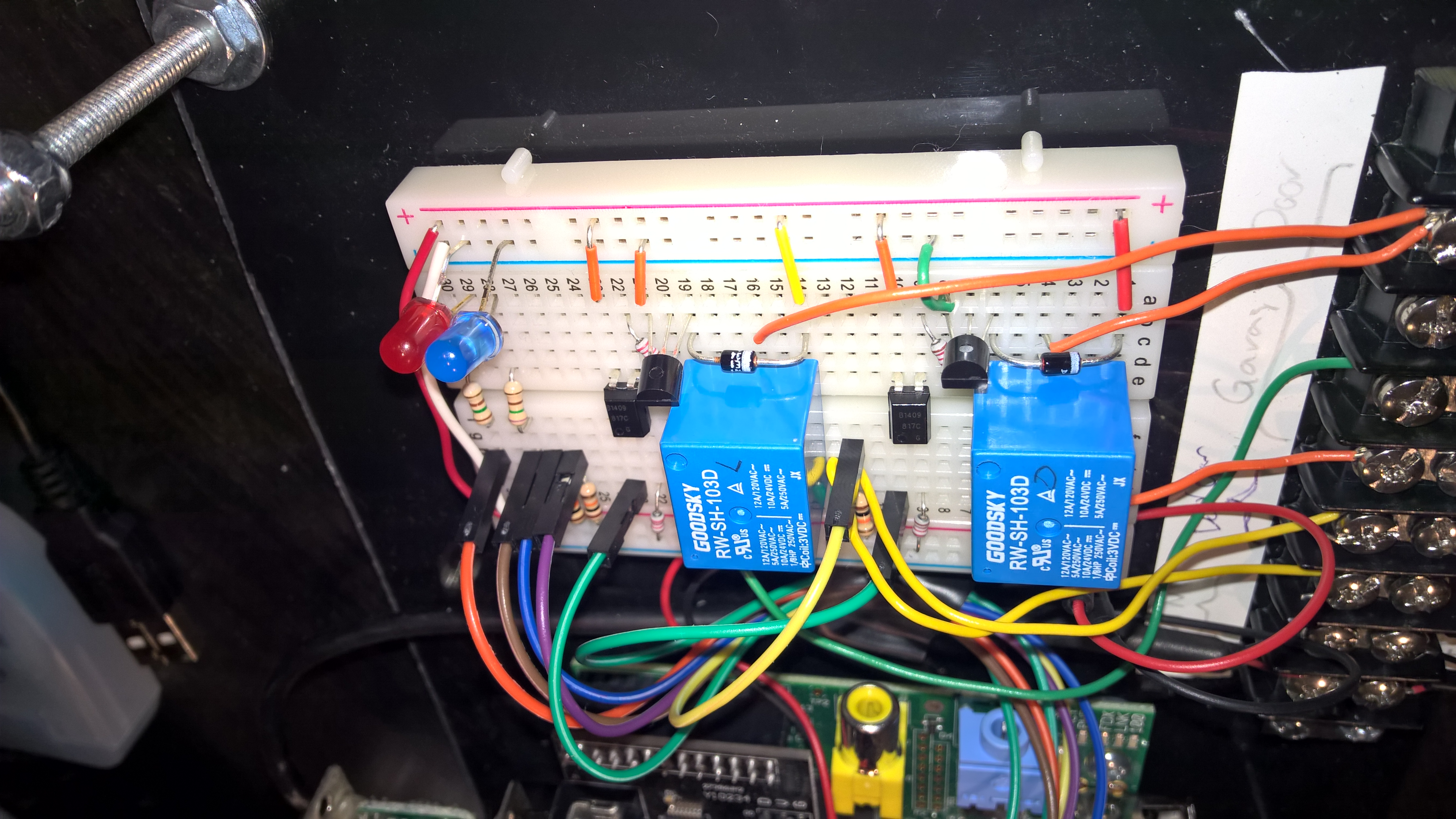
The second iteration two introduced some diodes and transistors, and then I was up and running.  I added a couple momentary contact switches to provide local light and door control, and picked up some DHT11 to do my temperature/humidity sensing.

I put everything together on a breadboard, with a plan to solder everything together and put it into a clean enclosure with my couple of surface mounted switches, but I quickly fell in love with the idea of just putting an acrylic top over it, and mounting the Pi and breadboard together on another sheet of acrylic (spray painted black on the back), as-is.  It has a fun look to it, and that might be what I like about the whole project most.

Second iteration of electronics using transistors, diodes, and opto-couplers

Second iteration of electronics using transistors, diodes, and opto-couplers

The one part that sadly hasn’t made the cut yet is the X10 firecracker.  This is a control device I used to have connected to my PC (back when I had a serial port), which works in conjunction with a wireless receiver to send On/Off power commands to outlets and switches throughout my house.  I found and installed an RS-232 shield on the Pi, but later found out that it doesn’t connect the RTS/CTS lines used to power and signal the Firecracker.  Oh well, I’ll think of something in the future…

The Software

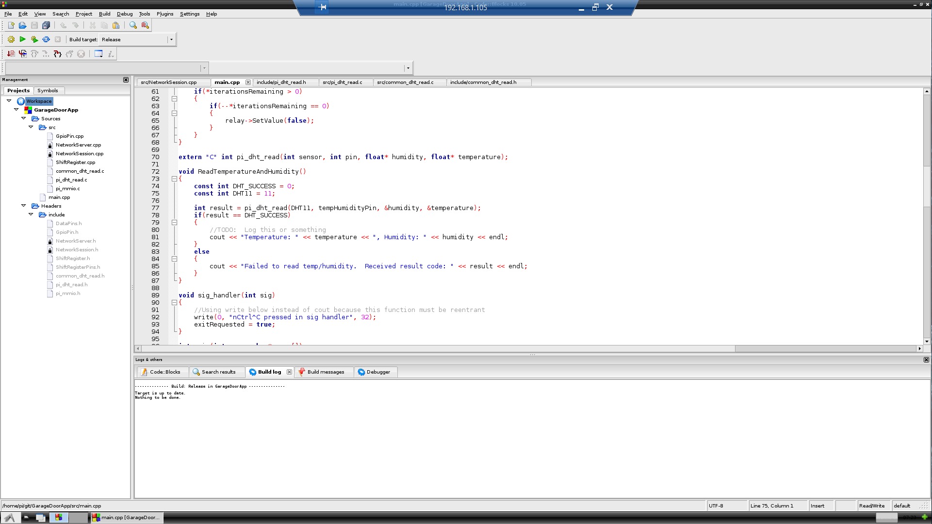
I chose CodeBlocks as my IDE of choice on the Pi, after seeing a few recommendations online for people coding in C++ on the Pi.  I was able to target C++ 11 features, and although it took a while to figure out how to get the Boost libraries to link up to my project, the process wasn’t too bad.  In general, however, I wouldn’t recommend that people try to write code directly on the Gen 1 Raspberry Pi, at least when you’re trying to do it using an IDE on top of x-windows.  It’s really slow, not only when trying to compile (which takes a long time even for trivial programs), but even typing code into the editor is noticeably delayed.  I eventually started writing and testing as much as I could in Visual Studio, and then bringing the code files over to the Pi for final testing and implementation.  For final debugging/testing I eventually ended up editing files using VI over SSH to skip the UI overhead on the PI, and that seemed much more usable.

Running CodeBlocks on the Pi

Running CodeBlocks on the Pi

I have the project checked into GitHub, and you can check it out here.  With any luck I’ll actually come back and check in some schematics for the hardware portion of the application, but for now at least the software is up there in case the Pi dies in the extreme heat of my garage over the summer.

Trying it Out

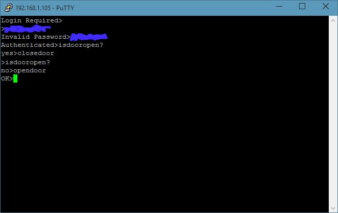
I was pretty excited the first time I was able to trigger the door and light manually using the new Pi-based controller, and even more so when triggering it from my desk.  The design has two LEDs, one that blinks on/off at roughly a one second interval, and one that lights red when the door is open.

Talking to the garage door using Putty

What’s Next?

In the next post, I’ll cover writing Windows Phone and hopefully a  Microsoft Band apps to talk to our garage door.

Open Source release of C# Spyder control library

The software library used for the Spyder Client for the Windows Store is now available for use as a nuget package (for .Net developers), and the source has been made available up on GitHub.  This library provides an implementation of the documented UDP control protocol, and additionally provides some of the ‘secret sauce’ used by richer control clients.  From the GitHub readme:

Key Features

  • Full implementation of the published Spyder UDP control protocol
  • System Config File parsing – provides full Spyder data object model to clients
  • Drawing Data (live view) data stream deserialization (Supports 2.10.8 – 4.0.4)
  • Spyder quick file transfer procotol (QFT) implementation. List, get, and set files
  • Thumbnail Manager – provides background downloading, multi-resolution scaling, and memory lifetime management of system thumbnail images

Consuming the Nuget Package (.Net Developers)

The Nuget package is the easiest way for .Net developers to consume the Spyder client library, and can be used to target Windows Phone 8.1 or later, Windows RT / Store apps, or .Net 4.5 or later desktop applications.  Get it from Visual Studio using the Nuget package manager (see screenshot below).

Nuget Package Info Page:  https://www.nuget.org/packages/SpyderClientLibrary/

Getting the Spyder Nuget Package

Getting the Source

GitHub Project Link:  https://github.com/dsmithson/SpyderClientLibrary

If you want to build the library yourself, peruse the source, or even port it to another platform, head over to GitHub to get access to the source code (link above).  This source uses the Apache 2.0 license, so you can do whatever you want with it.  Please do use the issue tracker or submit pull requests if you have anything you’d like to add or fix, and have fun!

What’s Next?

In future posts, we’ll explore some sample applications that use the library to do common things like control command keys, perform file backup/restore, and possibly even create a display simulator control that works from the Spyder server’s real-time data stream.  I’ll also be working on some general documentation that I’ll post on the GitHub site, so keep an eye on the project’s GitHub page.