Category Archives: Vista Systems

Building a Camera Tally Controller for Spyder in 2022

A whole 7 years ago I published a blog post and a couple YouTube videos showing a cool Tally (camera relay) system that anyone could make with a $35 Raspberry Pi device and $10 relay board. Back then this was running Windows on the Raspberry Pi 2 – a special stripped-down version of Windows called IoT Core that was designed to run on the Pi.

In seven years, a lot has changed. I started sprouting some gray hairs, Microsoft has all but abandoned Windows IoT Core on the Pi, .Net Core has become a mature way to deploy applications on Linux, and the Pi itself has had a powerful version 4 on the shelves for almost two years now. In this blog post, we’re going to modernize our prior approach and add some cool new features like a front panel display and a configuration/monitoring web interface.
Features and Overview

  • Works with Spyder 200 / 300 / X20 / X80 hardware
  • Works with every major release version of Spyder software
  • Supports different servers and rules per individual tally
  • Built-in web server for remote configuration and monitoring
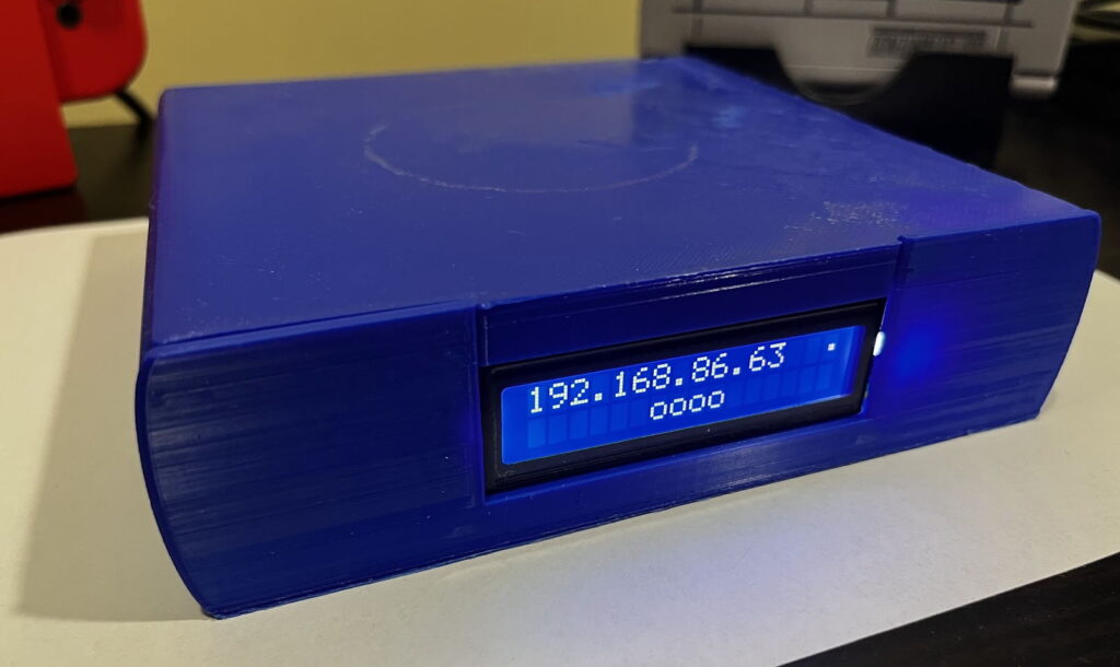
  • Front panel shows device IP and on/off tally icons for quick viewing of status

If you have a Spyder video processor of any generation, this device will work as a tally controller. For those wondering what tallies are, imagine a live show where multiple cameras are pointed at talent on a stage. Lights are usually physically positioned on top of the cameras and light up when a camera is ‘live’ to help the talent know which camera they should be looking at. The tally controller described here contains relays (electronically controlled contact closures) which open and close when specific sources are shown or hidden in windows on Spyder.

The video below walks through the device hardware and software, providing probably a better end-to-end overview than this blog post for those of us out there who prefer to consume video content.

Parts you Need

First off, you’re going to need to buy some parts. Here’s a list of what you need, some of which you may have around the house:

3D Printing a Chassis

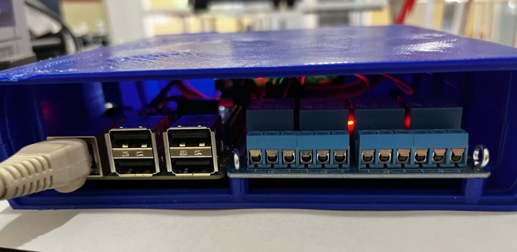
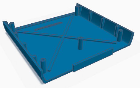
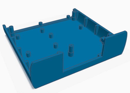
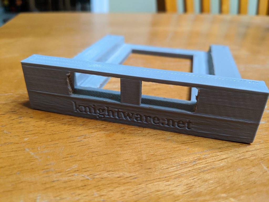
I used TinkerCad to design a simple chassis to hold a 4-relay board. You can copy and modify this design as you see fit, but for most folks you can simply download the 3D print STL files for the top and bottom pieces, and either print them yourself or send them off to a 3D printing service. If you watch the video from earlier in this blog post you’ll see the Raspberry Pi and the tally board are on the wrong sides of the chassis, and I’ve corrected this in the current design.

Chassis Top PieceChassis Bottom Piece
View in TinkerCadView in TinkerCad
3D Chassis Parts for Tally

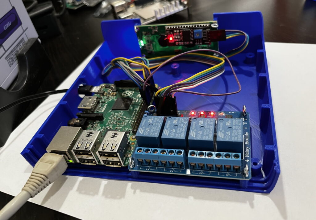
Building the unit is quite easy once you’ve acquired and printed the parts required. The open frame views in the video show off mounting the raspberry pi, tally board, and LCD front panel display in the chassis.

Wiring the pieces together

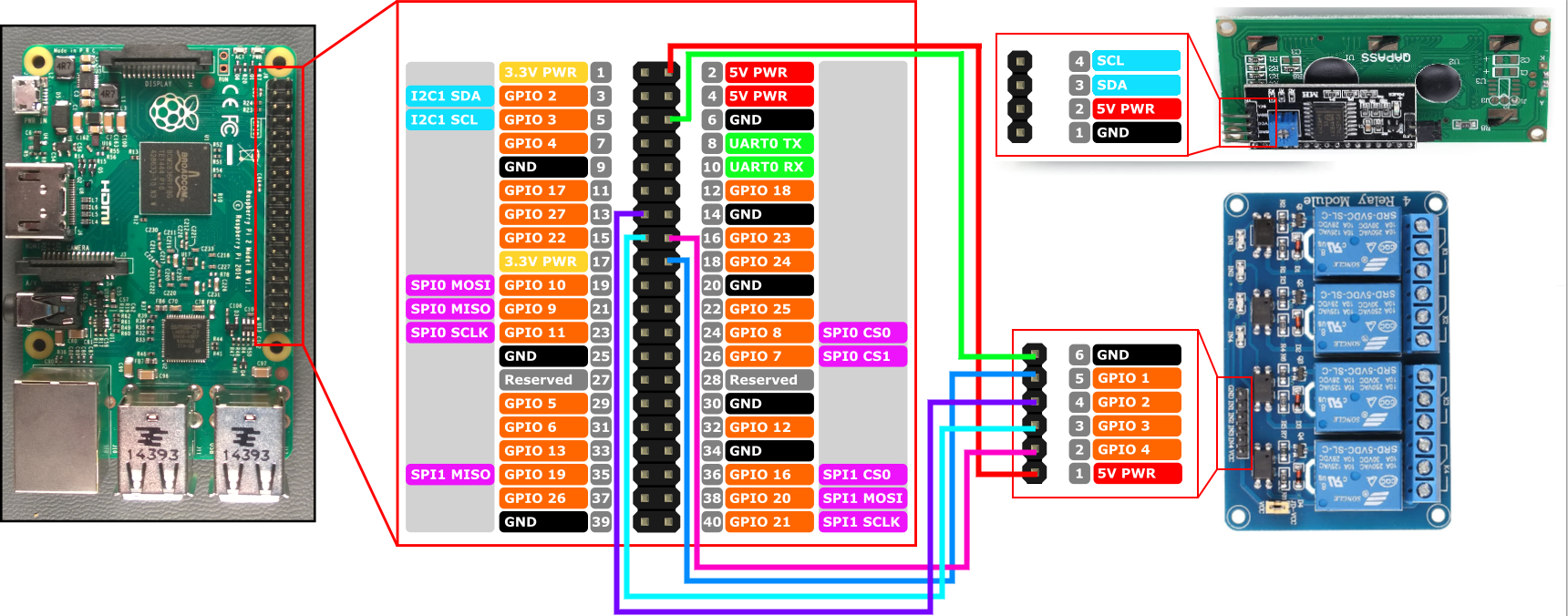
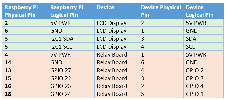
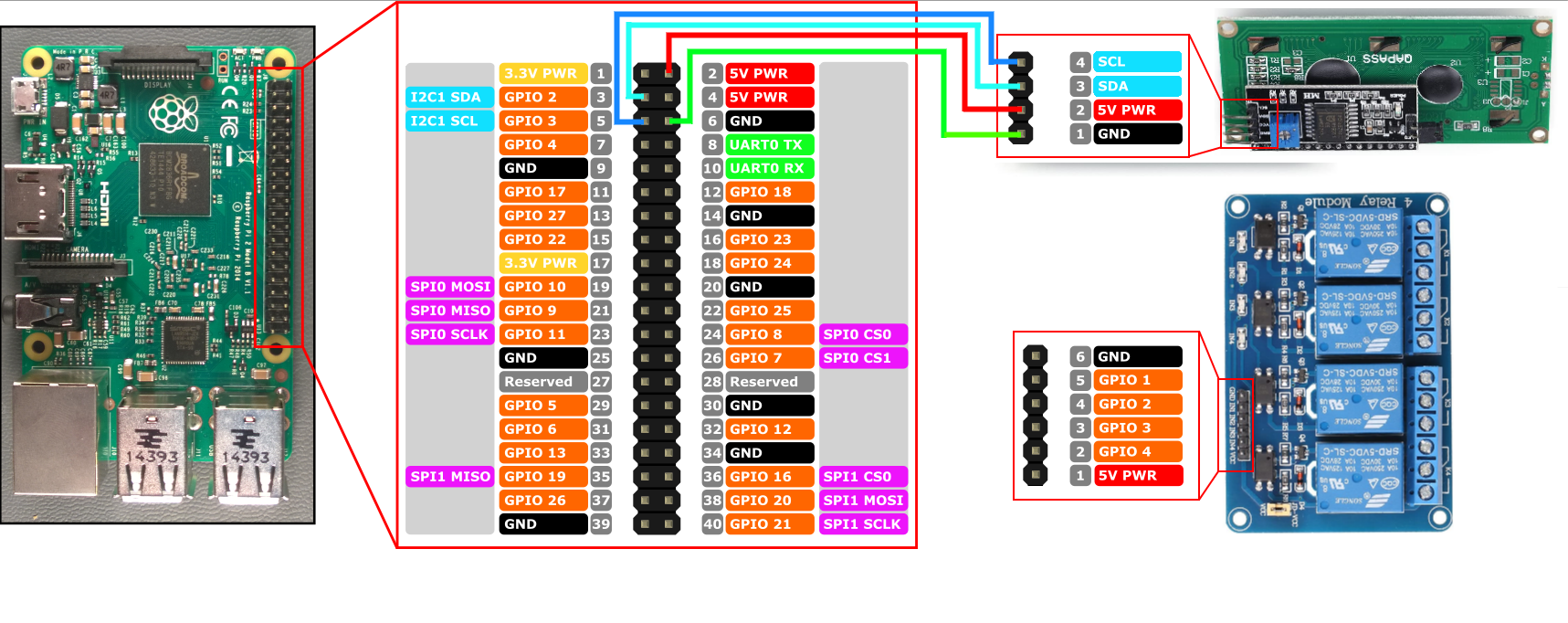
You can use simple breadboard style wiring connectors to save yourself from any kind of soldering, making the assembly a ‘Lego-like’ plug and play experience. The images below show the connections you’ll wire up from the Raspberry Pi to the LCD display and the relay board. If you’re creating a tally controller with more than the 4 relays shown, you’ll simply pick some more GPIO ports on the Pi for the additional connections (just be sure to write down which pins are connected to the relay pins for later configuration).

Spyder Tally wiring pinout
Wiring diagram for connecting Pi to the LCD display
Wiring diagram for connecting Pi to the Relay board

Installing the Pre-Built Raspberry Pi Software

Download SD Card Image for Raspberry Pi and/or release binaries here

Installing the pre-built software image for the Raspberry Pi is the easiest way to get going. You can download the SD card image directly from the Spyder Tally GitHub project’s releases page and use the official Raspberry Pi Imager tool to write that image file onto an SD card.

After writing the image file to the SD card, insert it into the Raspberry pi, connect an Ethernet (network) cable and power it up. It shouldn’t be necessary to connect a monitor to the Pi, but it does feel nice to keep an eye on it during the first boot where it will perform one-time tasks like expanding the file system to fill the SD card. That first boot will take several minutes, but eventually you should see the front panel light up and show the unit’s IP address.

Note that the software will wait for the network to become available before launching, and so you will not see anything until after the network is plugged in.

Installing Manually (Raspberry Pi or Other Devices)

If you’d like to use a device different than the Raspberry Pi, or if you want to build your own Raspberry Pi image for whatever reason, you’re in luck because it’s easy to do! The software may need some tweaking (particularly around hardware interface control) but should readily run on a wide variety of Linux devices including x86, x64, and ARM hardware with minimal tweaking.

The steps involved in creating your own disk image can be extrapolated from this README up on the project’s GitHub site.

One tweak I made when building the v1.0.0 SD card image – instead of installing the .Net Core framework on the device, I compiled the app as a ‘self-contained’ deployment. This kind of deployment bundles in all the .Net runtime pieces needed to run the application, and can both slim down the overall disk footprint and decouple the app from needing to be deployed on a target with a compatible .Net framework version. I like this approach and will likely continue this trend in future releases.

Summary

Spyder is an excellent product, and I’ve always been proud to have been a part of its history during my years at Vista / Christie Digital. Making accessory software and devices like this tablet controller still make me incredibly happy even years later. I hope you enjoy making your own as much as I enjoyed creating it. Let me know what cool environments you end up using it in!

If you run into any snags or have ideas for improvement on the project, the easiest way to communicate is to file issues up on the project’s official GitHub repository issue tracker. I do keep an eye out for comments and will try to reply as I can, but I tend to have a bad habit of not checking for comments for months at a time 🙂
ScreenMaster III 3216 – Restoring a Classic – Part 3

We’re going to keep the train moving in this post, and we’ll talk about taking the console interface software from the last post and connecting it to a message queue and finally to a new interface that will emulate the ‘Montage II’ console using by all variants of the Spyder video processor. By the end of this post, you’ll see a fully working console implementation. Better yet, project partitioning described here can be adapted to easily support different button board hardware, so stay tuned For those impatient like me, I’ve also put the final state demo video right below this sentence (you’re welcome).

First the obligatory high level picture of what we’re going to be walking through (below). On the console we’ve deployed three different applications running effectively as Windows Services. In reality the message queue writer and console emulator apps are running as scheduled tasks which launch on startup, purely due to it being easy to deploy, but they effectively are treated like automatically running services.

  1. ScreenMaster to Message Queue Writer: pushes hardware specific messages to a message Queue using standardized JSON messages
  2. RabbitMQ: Freeware message queue service maintained by a 3rd party
  3. Spyder Console Emulator: Translates messages between a message queue and a Spyder server. A Spyder server will think it’s talking to a ‘Montage II’ controller, which is the official console hardware platform for Spyder.

ScreenMaster to Message Queue Writer

Hardware interfaces come in all kinds of shapes and sizes, and in the case of the ScreenMaster III 3216 there is a hard-coded IP address scheme that makes it hard to develop and debug using a PC other than the built-in one. Other hardware interfaces, like on the ScreenMaster II 1608, use a serial connection inside the console between the hardware and the PC. Due to this, it became obvious early on that normalizing the specific hardware interface using standardized messages on a message queue would be a big help for development and debugging. Another positive outcome is that software can be written for any hardware interface, using any software language, and alas long as it implements the same standard JSON message structures it’ll ‘just work’ with the rest of the application stack.

The code repository for the message queue writer lives in GitHub here. As of this writing, the JSON message formats have not been documented, and so someone interested in making their own interface can look at the full set of classes in the messages folder for the existing project. The general messages from hardware to message queue include Key Action (press/release), Joystick Action, Rotary Action, and T-Bar action. Messages from message queue to hardware include setting lamp(s) on or off, and setting quick key LCDs (color and text). A key being pressed on the console, for instance, would generate a JSON message that looks something like this:

{
  "keyIndex": 102,
  "isPressed": true
}

The other message payloads are similarly simple. I encourage you to take a look at the GitHub project for details. It’s intentionally a small project, and should be easily replicated or adapted to work with other hardware consoles. Here’s a little demo using RabbitMQ’s built-in management interface to get and set messages to the ScreenMaster hardware.

RabbitMQ

I won’t spend a lot of time on this one, since it’s easily Googleable with Bing, but for those of you asking ‘What the hell is a Message Queue and why do I care’? The short version is that message queues allow multiple applications to send and receive messages between each other. There are several different implementations and vendors to chose from, but one (if not the) most popular offering is called RabbitMQ. I’ve installed RabbitMQ on my console, and it runs as a service in the background and launches when the internal computer boots. This works great for the message queue writer and Spyder emulator apps also running on the console, but it’s also REALLY great because I can connect to it from my desktop workstation for development and debugging. Before this I was actually slinging code directly on the console.

But wait a minute, you say, doesn’t putting a message queue between a hardware button board and some software processing create a noticeable degradation in performance? Short answer is no. Slightly longer answer (and in encourage you to look into it more if you’re interested) is that message queues are used as the backbone for enterprises and other environments like stock trading software that demand ultra low latency. There are some configuration options around delivery guarantees that can start to add up in some scenarios, but for our use case we won’t notice any performance impact.

Spyder Console Emulator

With the message queue in place, I have a bridge between a specific hardware interface and a generic messaging system. During that development, it occurred that it might make sense to make another application that would emulate a real Spyder console and translate between the message queue and the Spyder processor. It actually works quite well.

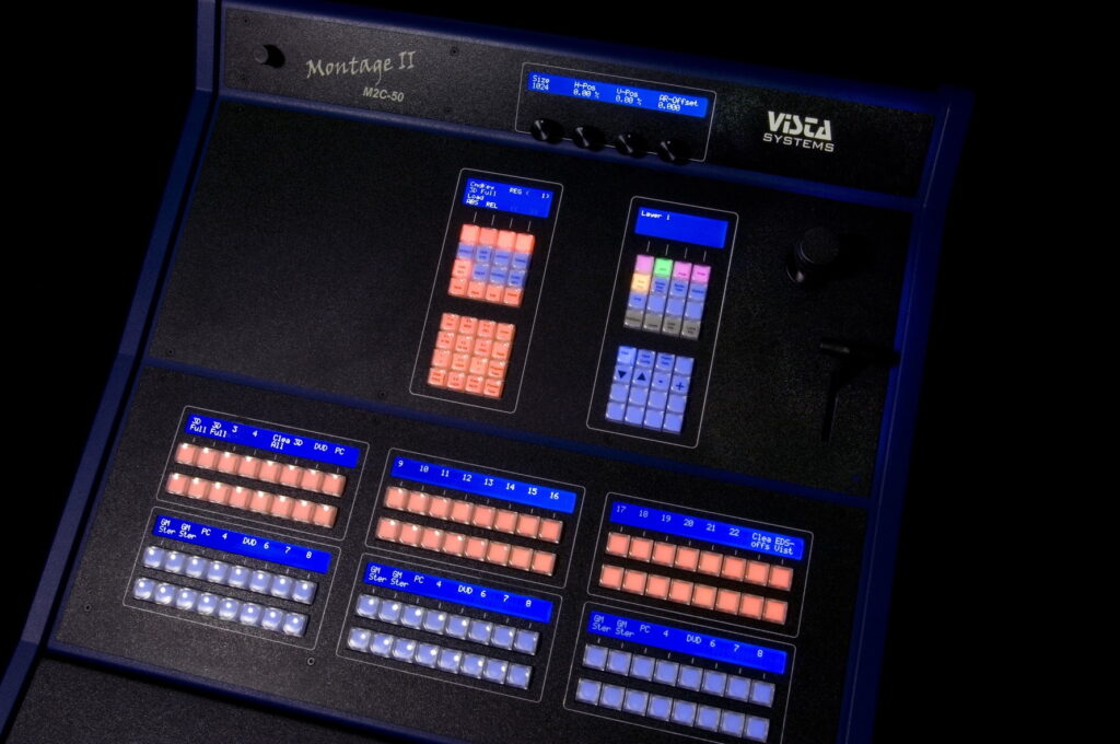
Quick (and relevant) history lesson. The ScreenMaster 3 (and subsequent Montage I console) drew a lot of criticism for having an embedded Windows computer. Other manufacturers (Barco comes to mind) took the opportunity to smear the product as being unreliable because of the internal PC. As a result, the Montage II debuted without any internal PC. The console is VERY simple – it has some simple menu capability to set a local IP and an IP for the upstream Spyder server, and listens for a handful of messages which set button lamps on/off (with an RGB color palette – see picture below) and set LCD text. It will also send network (UDP) messages to the Spyder when a button is pressed/released or if the joystick, rotary, or T-Bar position changes.

If you’re following along in the paragraph above, you may have noticed a couple things. First is that with the console effectively being a ‘dumb terminal’, the Spyder has to manage all of the console state and logic. Second thing is that the messages to and from the console follow a pattern quite similar to what I described earlier with the ScreenMaster to message queue application. Knowing these things, I decided to make one more translator; this time a translator between my message queue and the Spyder console interface.

To make this translation application, I need to do a few things:

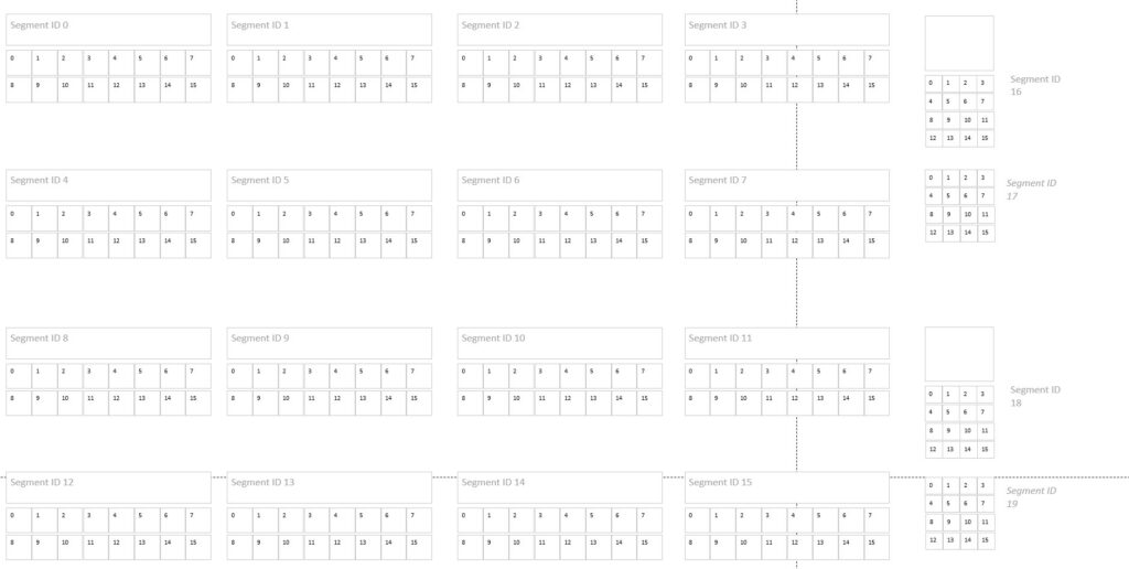
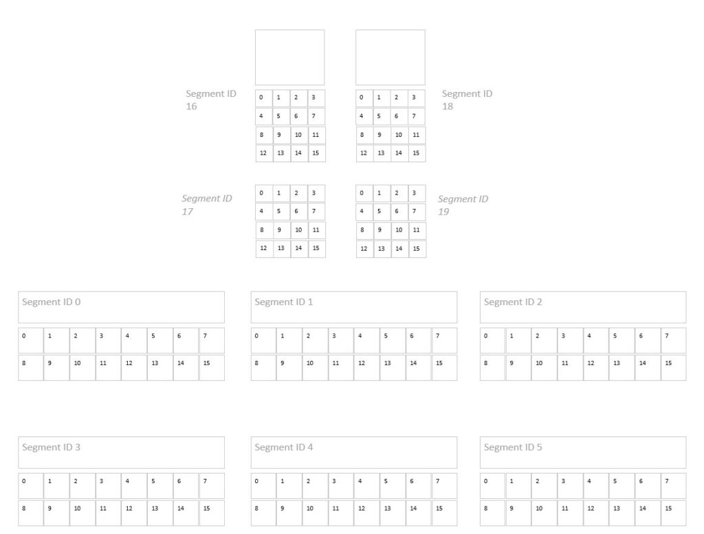
  1. Determine the button mappings used on Spyder’s Montage II consoles
  2. Define a mapping between buttons on the Montage II and my ScreenMaster console
  3. Write some software to emulate a Spyder console on the network so the Spyder hardware will actually think it’s talking to a console
  4. Make that software in the prior step interact with the message queue and translate messages back and forth.
  5. Add a key macro capability to the app which will ‘press’ the correct buttons to configure each of the segments of the console to ensure a desired state for the emulator.

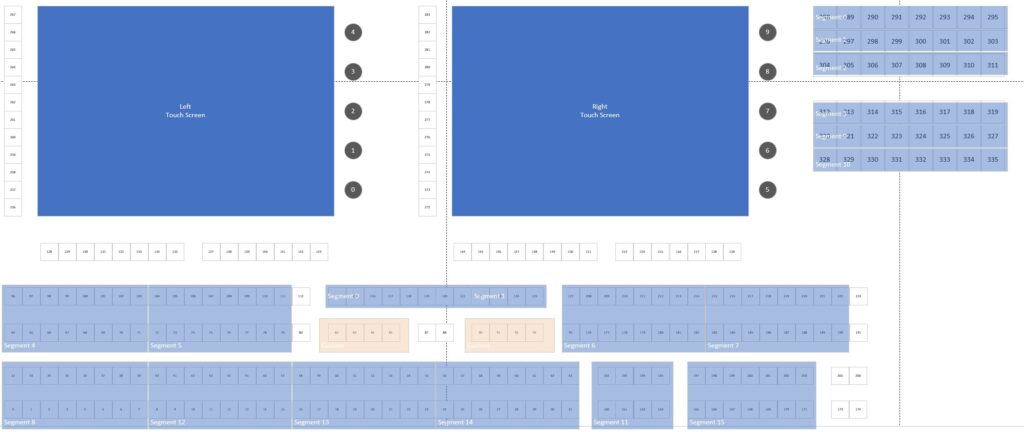
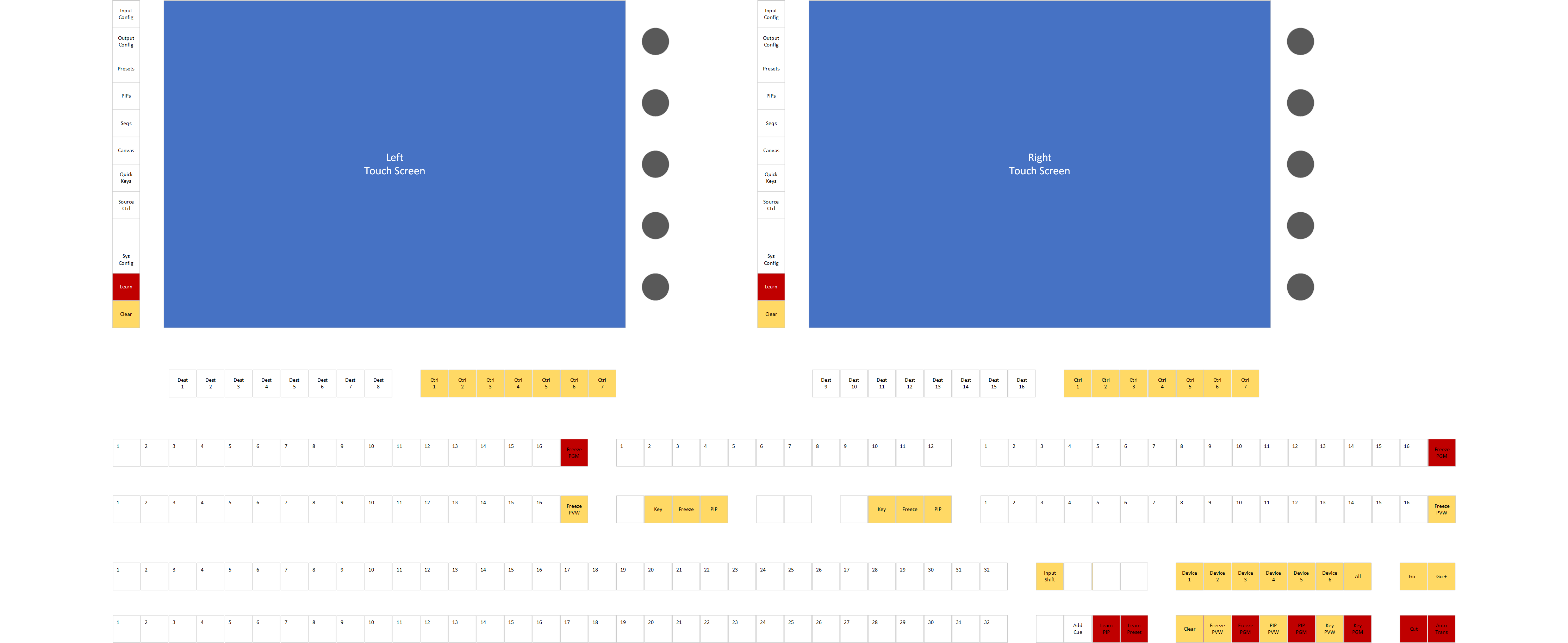
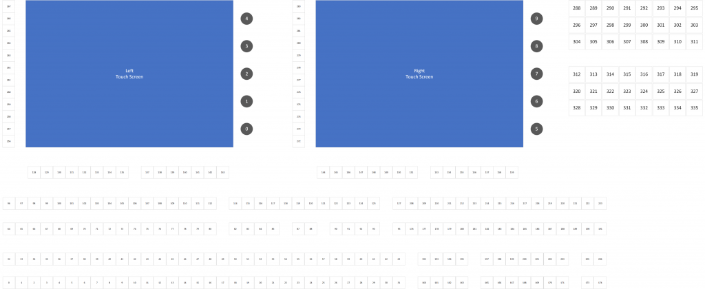
I created yet another Github repository for my ‘Spyder Translator’ with the code and relevant documentation. I created a Visio file with breakdowns of both the M2C-50 (smaller) and the M2C-100 (larger) console button assignments, and I also made a mapping of keys to my ScreenMaster console. Eventually this made it’s way into a JSON configuration file that I put into the repository, but a nice visual representation is always helpful for me. Some pictures from the Visio mapping doc below for reference:

The source code for the Spyder translator project in GitHub isn’t too crazy, and for those interested in looking further it offers a peek at a reference implementation for how the Spyder video processors communicate with networked controllers.

I’ll leave it to the reader to look further at the code repositories and refrain from turning this post into a code dump, but I’d love to hear from anyone who found it interesting or was able to build on it to incorporate some other cool hardware.

So Now Where are We?

At this point the ScreenMaster 3 3216 is an effective tool for controlling a Spyder video processor. The button mapping I’ve created has the quick key buttons mapped as Spyder Function keys, we have source selection and a full transition controller, command key and treatment control. Below is a walk-through video that I put up on YouTube to show off what the console is capable of. I was recording and trying to talk at the same time, so forgive me for the (low) production quality.

Now What’s Next?

The path I’ve gone down so far has been fruitful, but I very much would like to have some better and more native control of Spyder. There are some things I didn’t care for much with the Spyder controller, like only being able to access a single page of command keys or function keys, and not being able to create new items. This is due to the Spyder console never really getting much love – being a play-out device was generally just ‘good enough’.

All that said, I think it would be cool to make a ‘real’ control desk for Spyder, with full control of building things like treatments, command keys, and function keys. Deep integration of the screens to bring better selection context and more rich experiences would really make this thing shine. The timeline will likely come down to how much community interest exists, particularly now with the ability to relatively easily incorporate new and different hardware.

For now, thanks for reading and following along with my project. I hope it is able to tickle a few nostalgia bones out there, as it has for me. Until next time!

ScreenMaster III 3216 – Restoring a Classic – Part 2

In the first post in this series, we walked through upgrading the internal PC hardware within a ScreenMaster III 3216 hardware controller. In this post, we’re going to start creating the software to communicate between the internal computer and the hardware buttons, joystick, rotary encoders, and T-bar. All of the work discussed in this post lives in a GitHub repository that you can look through and use.

Before we dive in, let’s quickly agree on some terminology. I’m going to refer to the buttons, joystick, rotary encoders, and the T-bar collectively as the ‘keyboard’. Additionally, I’m going to refer to the Windows PC-based computer inside the console as the ‘host’. When we want to turn on or of a lamp for a button, for example, we’ll consider that to be a ‘host’ to ‘keyboard’ communication. Alternatively, when a user presses a key or moves the joystick a ‘keyboard’ to ‘host’ message will be generated. Hopefully this makes sense. Luckily the GitHub repository mentioned earlier in this post uses the same terminology in it’s documentation.

So how do we interact with the console hardware?

Communication between the host and keyboard is all performed using an internal Ethernet connection. This proved to be extremely helpful when upgrading the hardware, since we didn’t need esoteric connections to interface with the hardware. The keyboard has a hardcoded IP address of 192.168.1.3, and is hardcoded to send event messages to our host computer at the IP address of 192.168.1.2. This is quite limiting, but since it was initially designed to be an internal Ethernet connection we simply added a second USB network adapter during our PC upgrade dedicated to this interface. The image below shows the high-level Ethernet connectivity within the controller:

Over Ethernet, the messages between the host and keyboard are all simple UDP packets, with a very basic structure. I won’t detail the protocol here, but if you’re interested I’ve written up the protocol and published it within the GitHub repo here. Effectively, here’s the main list of things that you can do:

Host to Keyboard:
– Set lamp lights on or off for each button
– Set the LCD button background to Off, Red, Green, or some alternating combination
– Set the LCD button text – 3 lines, 6 characters per line

Keyboard to Host:
– Get event when button is pressed or released
– Get event when the joystick x, y, or z axis value changes
– Get event when a rotary encoder is turned (+/- change value)
– Get event when the T-Bar position changes

Time to write some software…

I’ve written and published a .Net Standard 2.0 library to implement the keyboard protocol and make it easy to consume from an application. The repository (listed at the beginning of this post) makes it simple to subscribe to events and control the simple pushbutton lights and LCD display buttons.

The repository contains a console test application that subscribes to events and writes these events to the console output. It’s a good example of how to use the library, and I’ve included a snippet of the test program’s Main function below for reference:

using Spyder.Controllers.ScreenMaster3;

static async Task Main(string[] args)
{
    // Initialize connection to keyboard
    var keyboard = new KeyboardInterface();
    await keyboard.StartupAsync();

    // Subscribe to events from the keyboard
    keyboard.TBarValueChanged += Keyboard_TBarValueChanged;
    keyboard.KeyPressed += Keyboard_KeyPressed;
    keyboard.KeyReleased += Keyboard_KeyReleased;
    keyboard.RotaryValueChanged += Keyboard_RotaryValueChanged;
    keyboard.JoystickValueChanged += Keyboard_JoystickValueChanged;
    keyboard.KeyAction += Keyboard_KeyAction;
    Console.WriteLine("Listening for events");

    Console.WriteLine("Press enter to exit");
    Console.ReadLine();

    Console.WriteLine("Shutting down...");
    await keyboard.ShutdownAsync(); 
}

If you’re playing along at home, you can pull down the library and build it from source, or for convenience I’ve also published it as a Nuget package for easier consumption.

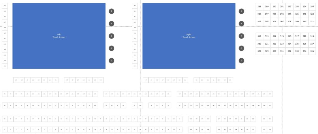
Mapping out the buttons

With a software driver library and a test application created, we can now go through the process of pressing and releasing every button on the controller, and watching the event data to determine the logical button ID associated with each physical button and rotary encoder. The console has well over 200 buttons, so it took a bit. My GitHub repo has a Visio document with some different pages that include the index map, and below is an image of this as well as a keycap map for the ScreenMaster III 3216.

Now where are we, and where do we go next?

At this point we have a controller with a modern computer inside, and we have a software library that allows us to interact with the hardware keyboard. With these in place, the real technical challenges are out of the way and we can focus on building an application to control something similarly modern. With my history and existing software libraries and software applications to control Spyder video processors, it’s probably not a spoiler alert to say this is where I’m heading.

I’m not sure yet if the next blog post will be software heavy (yet) – I’m planning to spend some time planning a good console application before diving too far into code. That being said, I couldn’t resist getting some simple app(s) started. As such, I’ll leave you with a quick video showing an app framework that works with the keyboard interface and is setting the selected page based from menu button presses.

If you’re still with me reading through this blog series, thanks! I don’t expect this project to amount to much more than a love letter to an old product that holds nostalgic value to me, but I hope it might resonate with a couple people out there. And if you’re lucky enough to have one of your own ScreenMaster III or a Montage controller lying around, let me know about it!

ScreenMaster III 3216 Console

ScreenMaster III 3216 – Restoring a Classic – Part 1

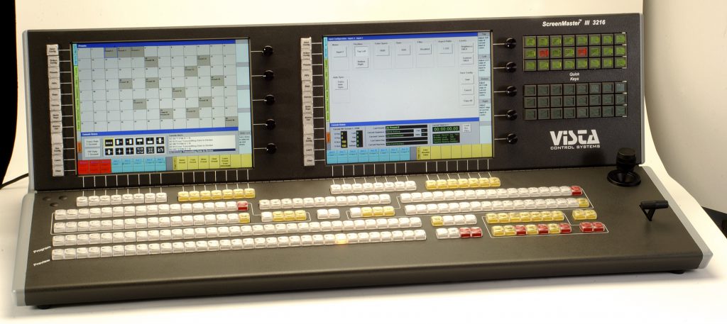
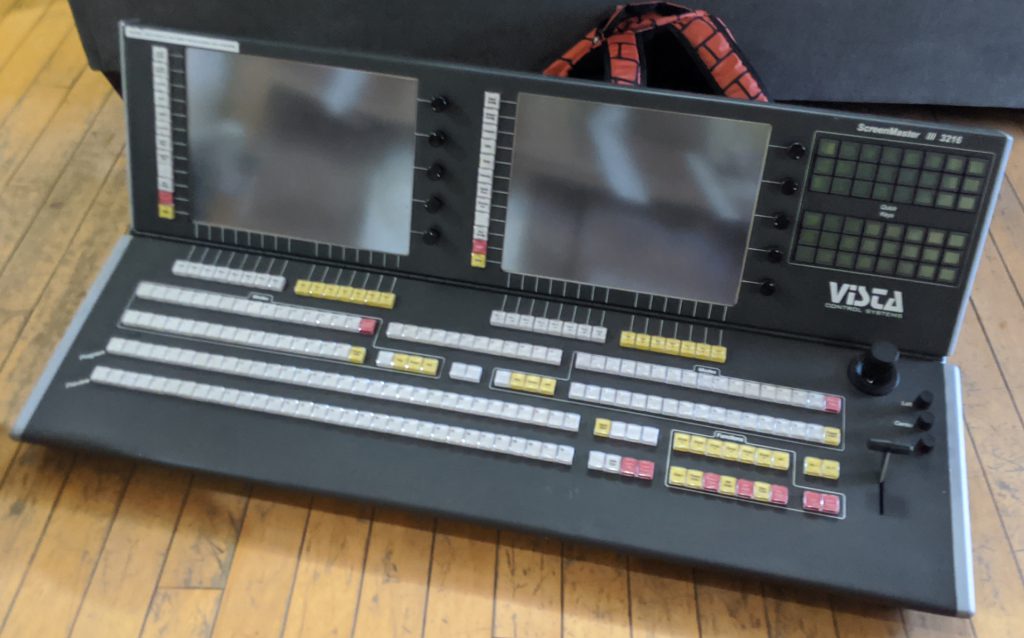
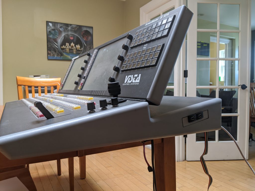
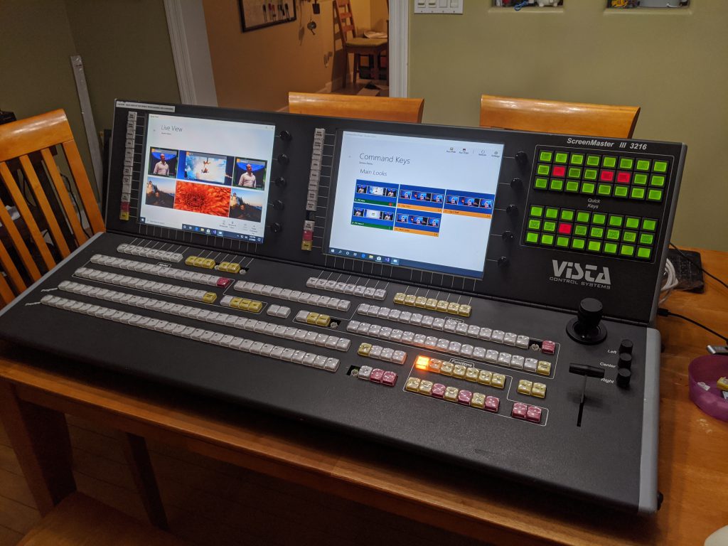
The ScreenMaster III 3216 and it’s half-sized little sibling the 1608 were some of my favorite consoles every made at Vista Control Systems (later renamed to Vista Systems and later acquired by Christie Digital). These were the first consoles to incorporate 15″ touch screen displays to compliment the massive button boards from prior console generations. This console, like others before it, were purpose built to control a combination of Folsom (now Barco) VFC-2200 scalers and either Extron, Pesa, or Sierra routing switchers. We’re talking analog video only here – this was the nineties after all, when 1080p video was king.

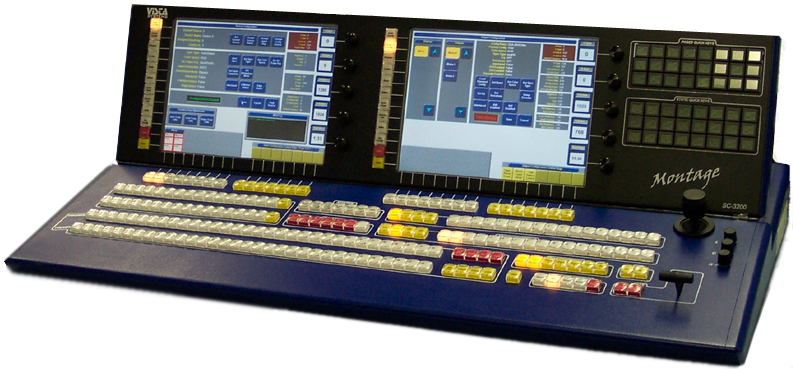
It’s worth a note that this console would be appear again in the future as the control surface for the Vista Montage video processor, painted in blue and re-dubbed as the Montage SC-3200 console. This stuff is all but lost in time, even on the internet these days, and so I’ve included a picture below for full historic reference.

Let’s talk about this got started

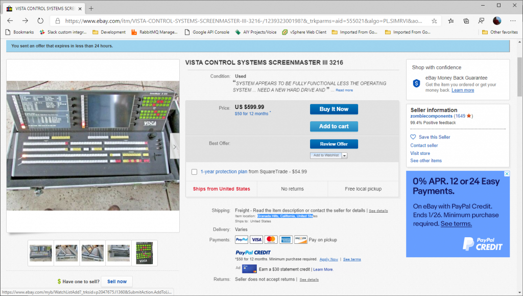
Let’s talk about eBay. eBay is a great place to get great deals, and is a great place to troll late nights when you can’t sleep to find stuff you didn’t know you needed (and probably don’t need). One night I happen to be aimlessly looking around the internet, and somehow I made it to this posting on eBay:

This picture of the console immediately gave me ‘the feels’, as it has solid sentimental value. I remember shipping the first of these consoles, sometime back in the nineties. We had a problem with a driver for an internal USB network adapter, and it was causing the console to bluescreen. We weren’t sure it was fixed, but I ‘thought’ I had resolved the issue with an updated driver. We got the console in it’s case and brought it to the back door. After talking a bit about this bluescreen, Jeff Wilson and I opened the console up and made sure it booted successfully five times. As long as it could boot five times in a row, then we’d ship it. Good news – that was the day unit #1 shipped.

<rant>Just to touch briefly on that last point – this was a time when Windows was considered to be generally unstable, and we caught a lot of flack from rental and staging customers (and competitors). Here we were though, shipping a device with Windows (NT Embedded I vaguely recall) and asking customers to entrust their high-dollar live events on it. Software bugs aside, I think this ask proved to be a reasonable one and these consoles were way ahead of their time (my opinion). </rant>

So this console on eBay had an asking price of $599, and I sent an offer for $299 which was accepted. I don’t remember the real figure, but I think this console cost around $45,000 new. From the pictures I could see some button-board activity and a boot failure, and so I knew that (1) the embedded part of the console was alive and (2) the PC was ‘alive’ and the Compact Flash card we used for the hard drive had likely failed. After some back-and-forth on the shipping, we decided to drop the shipping case to avoid going freight, and all-in I think I was down $500.

The arrival

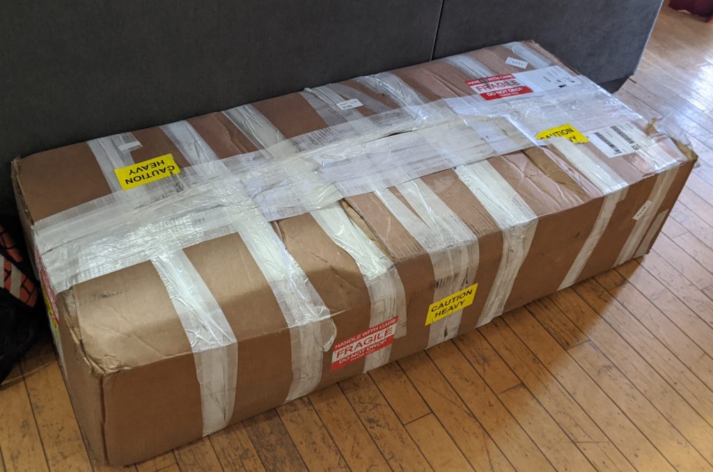
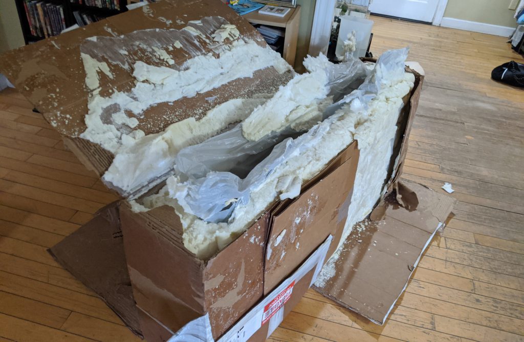
It took about a week for my console to arrive, and it showed up packed tight with instant-foam in a box that must have had a roll of fiber tape for additional support. It took a solid hour to practically chisel the console out of this foam tomb, but it shipped in pristine condition so I can’t complain.

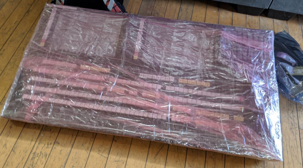
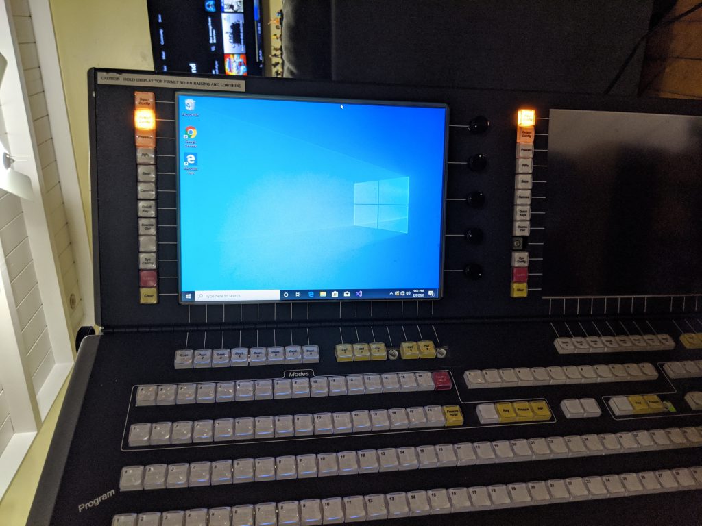
After getting the console freed from it’s shipping cocoon, I gave it a good look over and powered it up. The screen showed the same hard drive failure message that I saw on the eBay post. The quick-keys (the top-right green button array) showed diagnostic counters that I was able to use to verify that the buttons, joystick, T-bar, and rotary encoders were all functional (minus a few burnt-out incandescent switch lamps). So far so good. Next up is to take inventory of the computer hardware and try to get it working again, but before we move on go ahead and take a hard look at that good-looking piece of hardware 🙂 .
Console internals

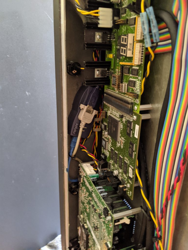
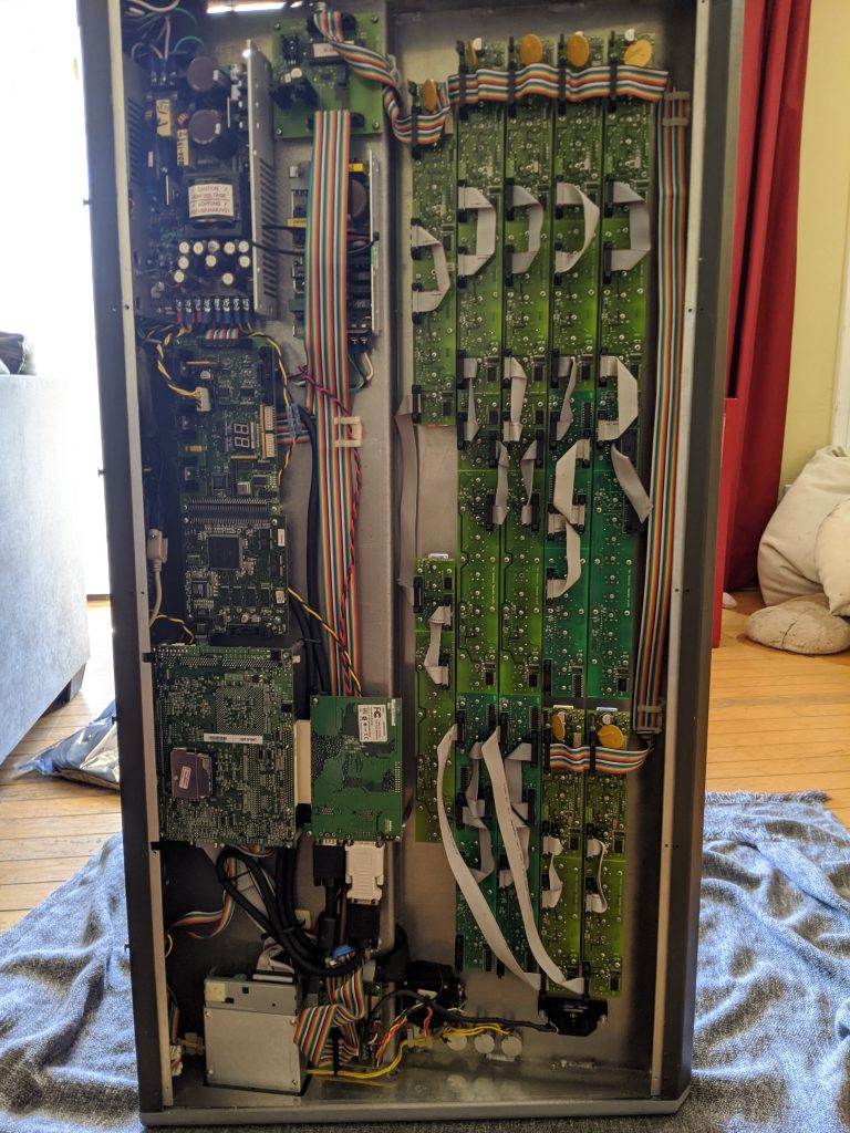
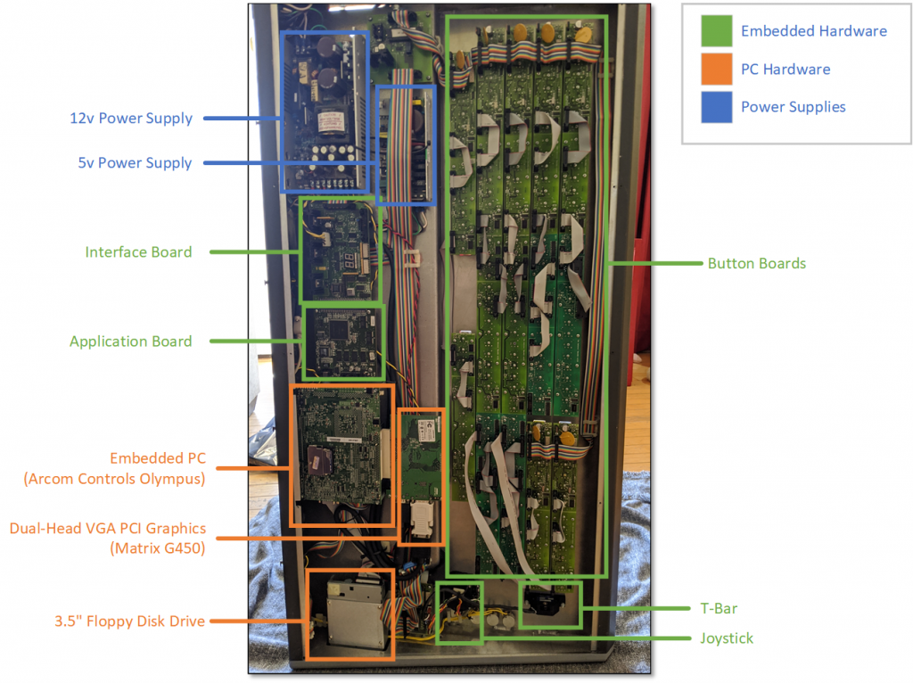
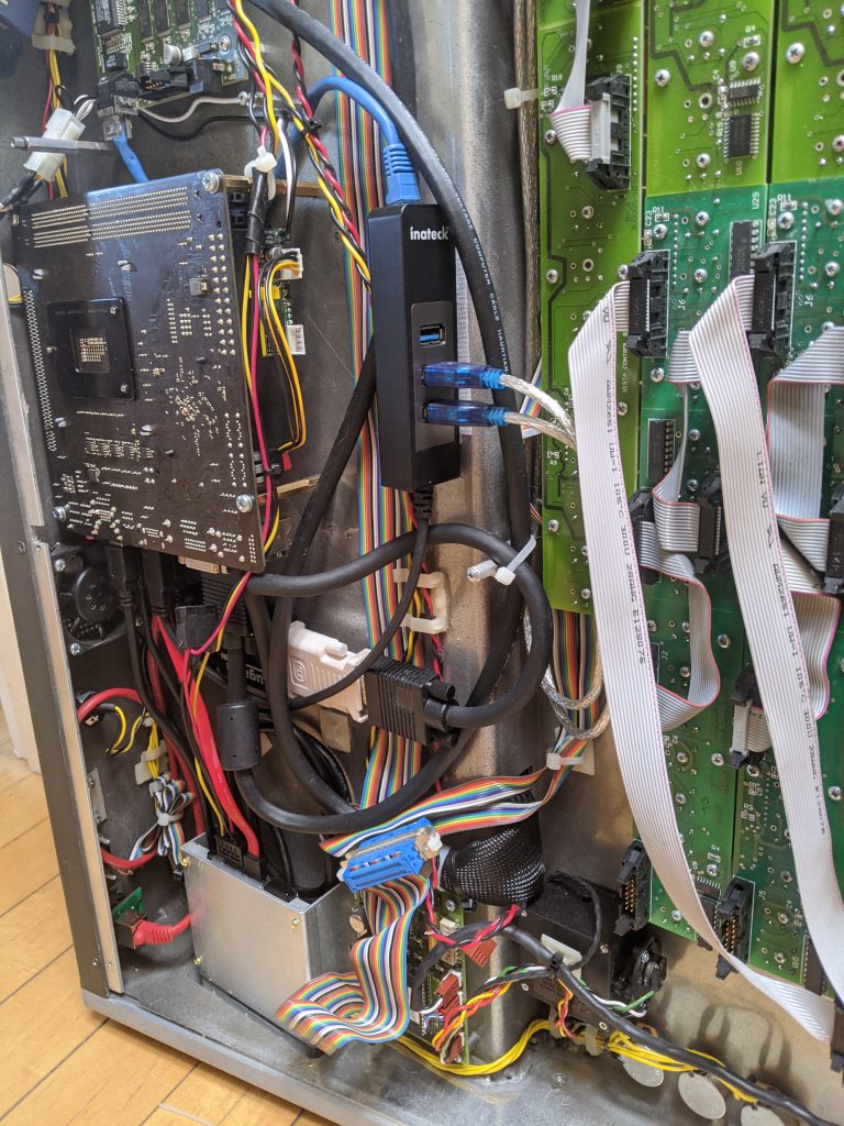
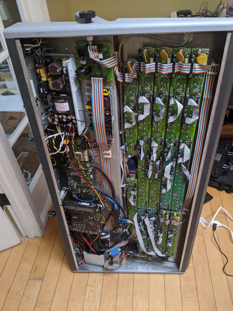
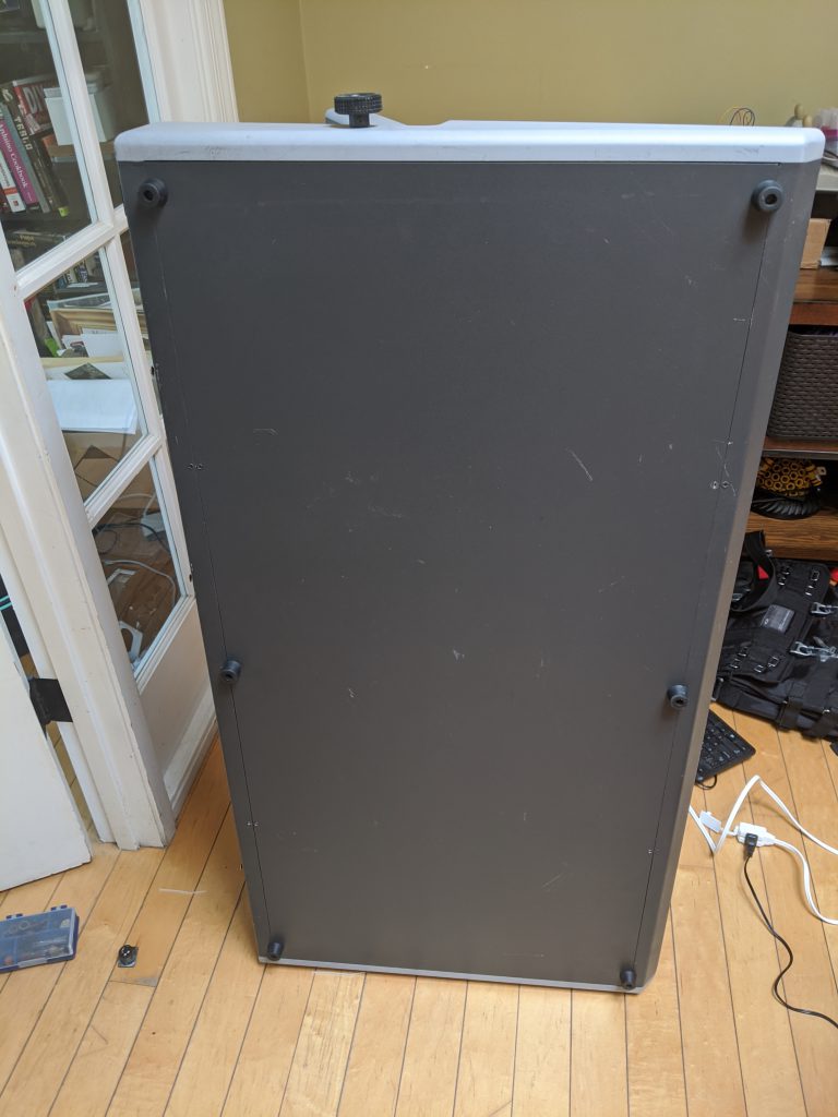
When you open the bottom of this console, you immediately see that there is a LOT going on. Luckily, when we look closely at the internals of the console there are two main subsystems – the embedded computer (PC) and the physical control interface (buttons / T-Bar / Joystick) subsystem. The picture below shows the console on it’s side with the bottom removed.

The application board is the main embedded component which houses the programming required to read and write the physical hardware. Luckily for us, the interface between the embedded computer and this application board is Ethernet. It’s difficult to see in the pictures, but there is an Ethernet crossover cable between a second Ethernet port on the SBC and the application board. This is great, because it means that we can upgrade the embedded computer without worrying about obscure hardware interface dependencies.

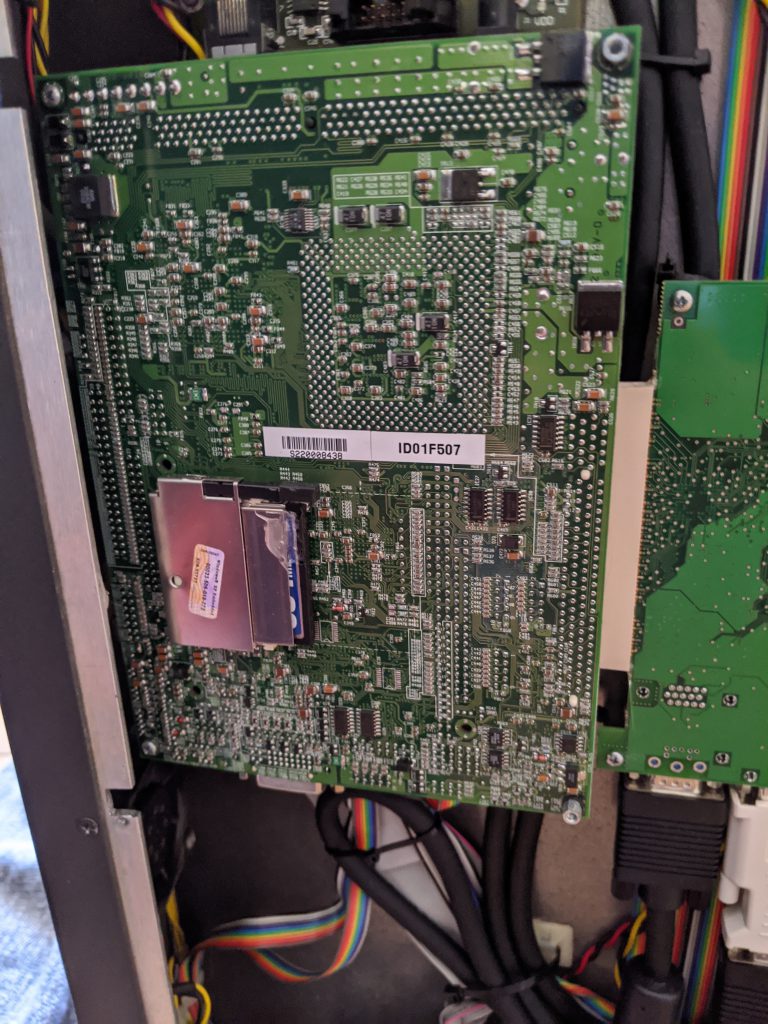
Before we move on to replacing the embedding computer, let’s take a second to talk about the embedded computer that came with the console. This was an EBX form factor computer called the ‘Olympus’ and was manufactured by Arcom Controls (datasheet here). This was a 1.0 Ghz Celeron processor and 128MB of RAM. The hard drive was provided with a 128MB Compact Flash card, which has limited read/write cycles and almost certainly explains why the console eventually stopped working. I did try jump-starting the console with a new Compact Flash module, but the SBC was so old that it felt that even if I could run a modern operating system on it (unlikely) that it would be terribly slow. It was also sporting a 3.5″ floppy disk drive, for those of you who remember what that even is, and I knew that needed to be brought into the modern age as well. With that back-story out of the way, let’s get to upgrading.

Upgrading the Embedded Computer Hardware

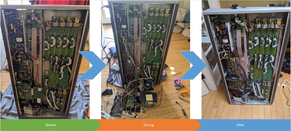
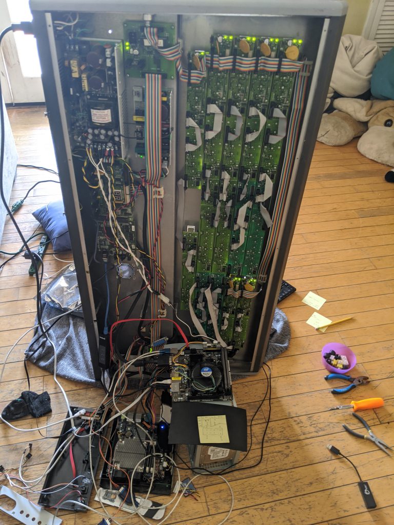
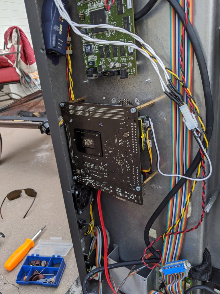
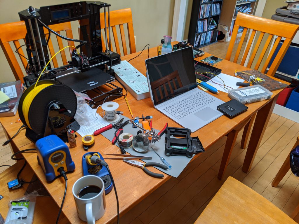
Full disclosure here – this console sat on it’s side in my living room for several weeks, and I’d give it occasional blocks of evening and weekend time. This wasn’t particularly hard, but there were some time-consuming parts of the effort that I’ll bullet point rather than writing a book about:

  • Removed the prior EBX form-factor PC board and graphics adapter
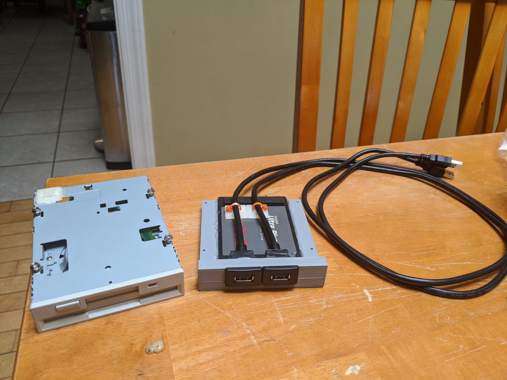
  • Removed the existing floppy disk drive
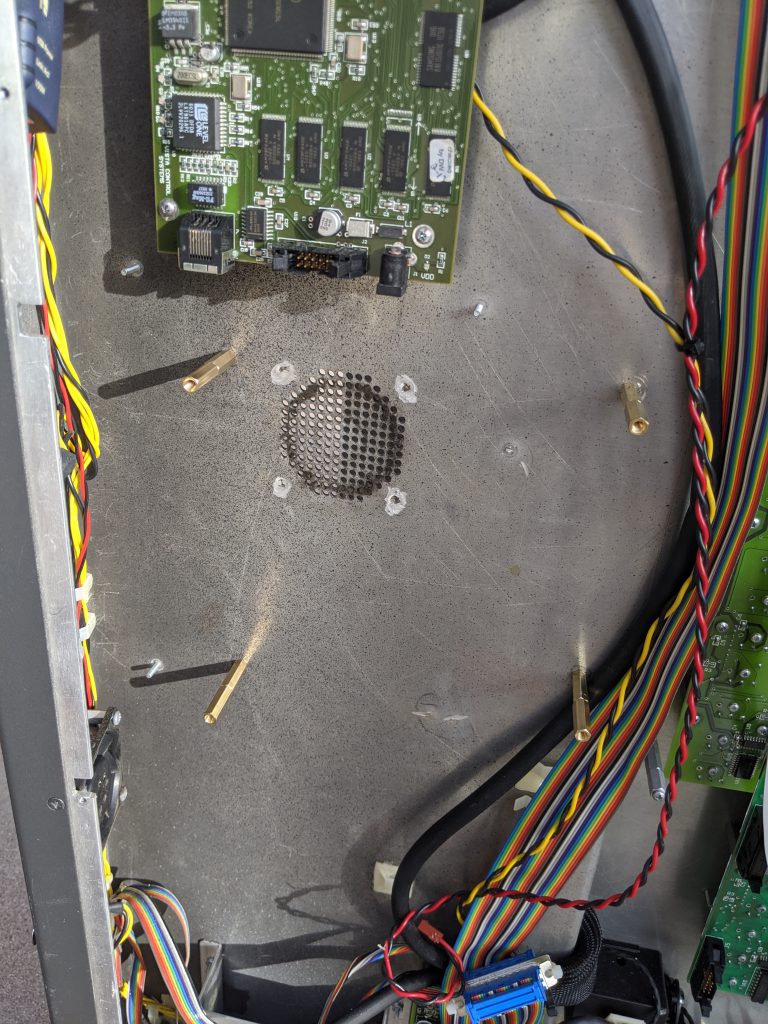
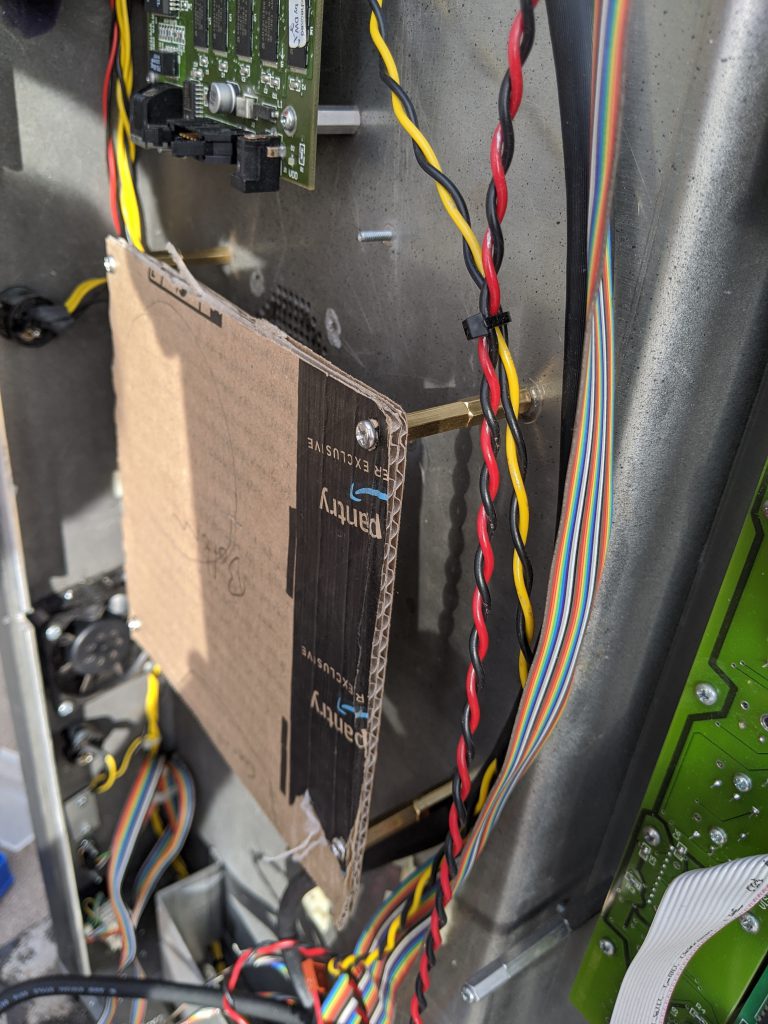
  • Drilled holes in the chassis to fit a new Mini-ITX form factor PC
  • Bought a +12V to ATX power adapter module to power the new SBC
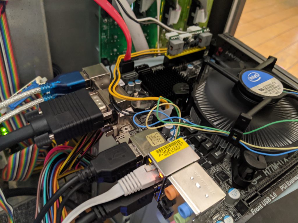
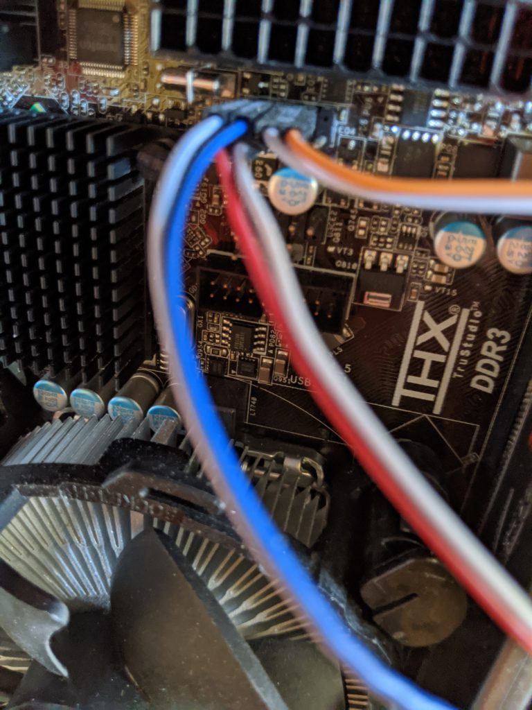
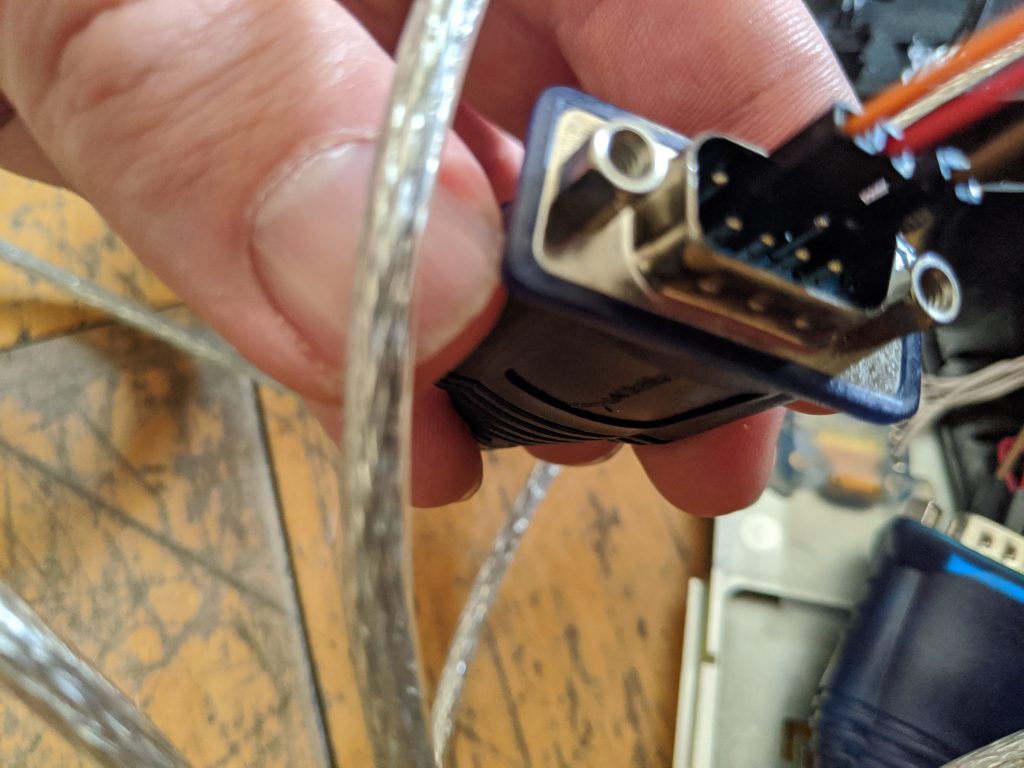
  • Added two USB to RS-232 cables to drive the touch screens
  • Added a USB to Analog adapter to drive the second touch screen (the SBC had one VGA port I was able to use as well)
  • Replaced the Neutrik Ethernet connector running to the back of the console with a new one
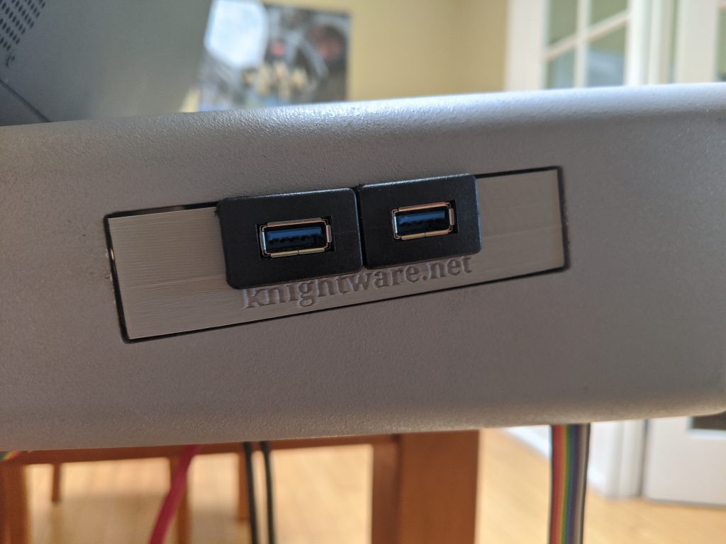
  • Modeled and 3D Printed a custom bracket to hold a new Solid State hard disk and expose 2x USB 3.0 ports to fit in the old floppy disk drive spot.

The mounting and retro-fitting of the new SBC and parts was a pain, but I’m pretty happy with how it came out. This thing feels like it could travel and be as reliable as the original console was. I am particularly proud of the 3D printed module that I made to hold the hard drive and expose a couple USB ports, and you can see this along with a bunch of other build pictures below

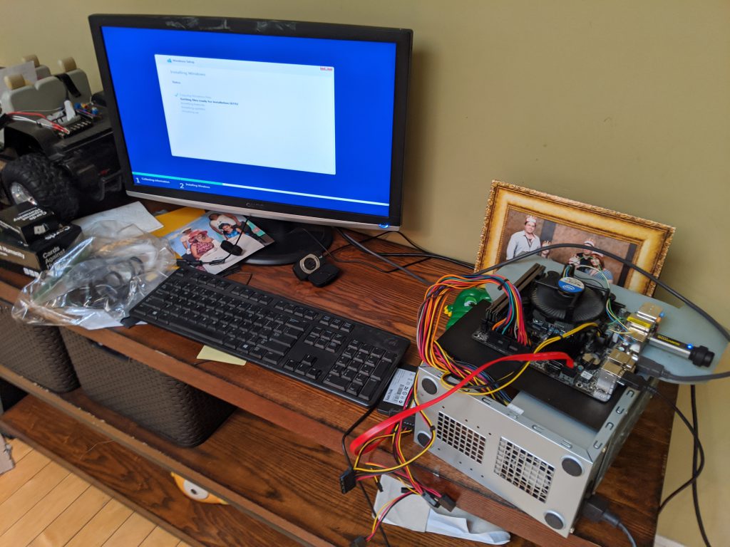
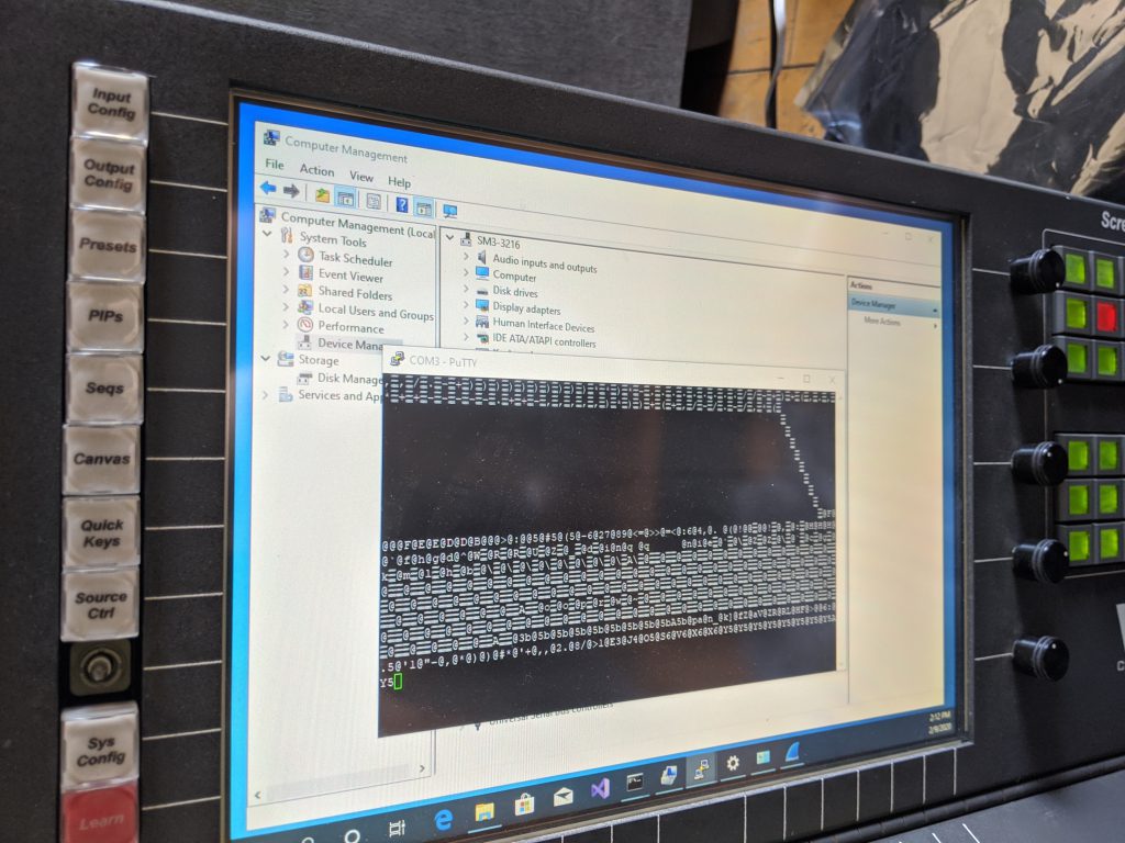
After the aforementioned evenings and weekends spanning may weeks, the hardware for the console was done. It was now sporting an Intel i7 processor with 16GB RAM and a 512GB solid state disk, and was running quite nicely. I did sneak in a picture of installing Windows on the replacement Embedded PC / Single Board Computer (SBC), but I’ve saved this for the last section of this post.

Let’s put Windows 10 on this thing

A modern console needs a modern operating system. I actually considered installing Ubuntu Linux for the fun factor, however ultimately I decided to install Windows 10 Pro. It’s less ’embedded’, but it allows for wider flexibility for software to run (including Vista Advanced / Spyder Studio / Spyder Client software).

One wrinkle that I did run into was around the touch screens. They have RS-232 serial controllers, and the native 3M driver didn’t work. I remember running into this with my Car computer touch screen (same hardware), and so I knew I needed to pony up and buy a license for a software called touch-base that makes the touch controllers work with Windows 10. Related note – the screens for the console are each 1024×768 resolution and VGA, and if I were braver I would crack open the top and try to replace them with some newer displays. Maybe someday.

Big reveal time

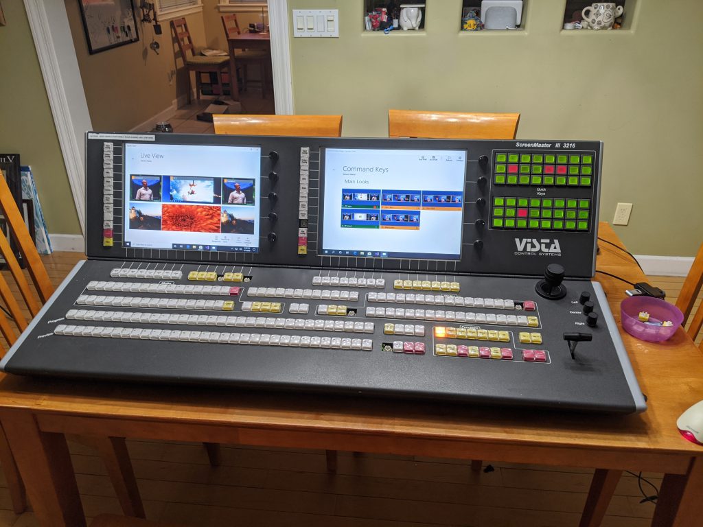
I don’t need a lot of words for this – I’ll let the pictures of the console working speak for themselves. For those curious, the pretty looking Spyder control software is the Spyder Client application that is available on the Windows 8/10 Store.

So where are we, and what’s next?

So we have a large powerful hardware console alive and well, and we have a working PC operating system on it. Probably a way over-powered PC in there hardware spec-wise, but we still don’t know what we’ll do with it so hard to say. By the time I write this, the console has actually been sitting in my dining room for the past two months. I’ve already done some development and created a software interface to integrate the hardware with the PC, but I’ll save that for a future blog post.

In the next post, I’ll talk about how the PC-to-embedded hardware interface works, and we’ll probably have a simple app to show take a look at. I expect the next post will be a bit shorter – this one was a monster and it feels like it just skims the surface. With that, thank you for reading and see you next time!

Building a Camera Tally Controller for Spyder

Over this past weekend I set out to create a camera tally device for the Spyder video processor.  Specifically, I wanted to try to use my relatively new Raspberry Pi 2 board running the Windows 10 IoT Core operating system to make something useful.  If you’ve read through my older blog posts, you’ve likely noticed that the Spyder is still my go-to target platform for playing with new technologies.  Let’s face it – when you’re playing with shiny new toys, it helps to mate it up with something you know very well so you don’t feel completely lost.  Before I get into the details, check out this brief video showing a working tally controller in action:

The whole process of building this device was simply fantastic.  The barrier to entry for people making hardware devices has gotten incredibly low over the past couple years, both from a cost and ease of development perspective.  The whole build process was very quick, and I had such a great time with it that I went ahead and put together a full 30 minute hardware and software video walk-thru for the project (more on this below).

Getting Started Making your own

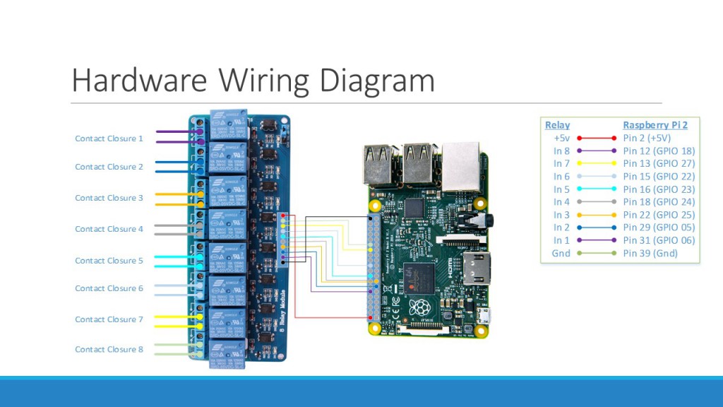
To get started making your own, here are a couple links for the main hardware used on this project, as well as the wiring diagram for your reference.

Raspberry Pi 2 Kit ($70):  Amazon Link
8-Channel Relay Board ($9):  Amazon Link

Tally Wiring Diagram

Hardware Wiring Diagram for our Tally Controller

Links to the full source code, documentation resources, and a full YouTube walk-thru video are below.  This video has a ton of valuable information in there, covering the hardware specifics, Spyder implementation details, and the full process of creating our software application.  This is the first time I’ve gone through and made something this elaborate (and narrated the video), and I’ll be very interested to know what you think of it (so leave me a comment below if you’re so inclined).

GitHub Project (Source Code and Documentation):  Click Here

Next Steps

The tally controller we’ve created is certainly functional. but in it’s initial form the server IP address and tally source lists are hard-coded.  In the next stage of this project, we’re going to build a desktop application that can connect to the device remotely over the network and view/configure these properties.  We’ll also explore creating a user interface to run on the Pi’s HDMI output, which could be useful for monitoring and troubleshooting the device.

Until next time, take a look through those walk-thru video and the resources in the Github repository, and try to make one yourself.  I hope you enjoy going through this content as much as I enjoyed making it.

Spyder Client for Windows 8.1 – Live Control

One of my favorite areas working on in the Spyder Client for Windows 8.1 was the live view, which not only shows a real-time visualization of the Spyder server’s PixelSpaces, but allows for live interaction and command key creation. While it’s not necessarily new, I thought it would be fun to create a Camtasia video showcasing the live control available from the Spyder Client.  I certainly enjoyed making it, and I hope you enjoy watching it (and using it).

Under the Hood – Leveraging Spyder’s External Control

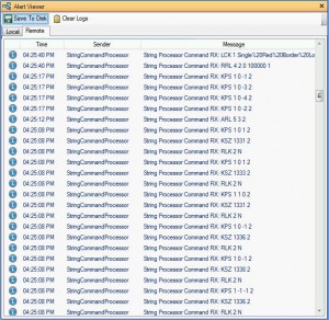
Internally, the Spyder Client uses the Spyder server’s publicly accessible external control protocol for all control actions performed by the application.  This is for a few reasons, one of the more notable of which is that Windows Store applications do not support .Net Remoting (which is how the Vista Advanced client communicates to Spyder).   If your curious how the Spyder Client is doing something you can simply check out the Spyder server’s logs to see what commands are being executed (see screenshot below).  Just make sure to set the server tracing level to information or success so that the command logs actually appear.  Of course, if you have a specific question, feel free to leave a comment under this blog post.  I’m always happy to help out a fellow coder.

Viewing remote server logs in Vista Advanced

Viewing remote server logs in Vista Advanced

Just in case you don’t already know, the external control protocol documentation is included with the installation of the Vista Advanced client software. If you have Advanced installed, then the external control protocol PDF document is already available from your start menu.

First App in the Windows Store (Yes it’s another Spyder Client)

Historically, when I’m taking a new platform or development tool out for a spin, I end up creating a control client for Spyder.  It’s nice to be able to work against a well-known and well-understood platform, so you can focus on the new and exciting stuff.  In this case, which is no exception, I fired up a Windows Store application targeting the Windows 8.1 platform.  In all truth, I think I started this about 5 months ago, however the project didn’t make real traction until the week of Christmas this year (which I took off from work).  I put forth a hard goal of getting the application into the store by the end of that week, in hopes that I wouldn’t aimlessly squander away my week at home.  At the end of the week, a new application had indeed been introduced to the store, and while it’s pretty ‘fresh’ I’m proud of the results so far.

Check out the app’s official page on this site here

Check out the app and download it from the Windows Store here

Feature Set on Day One (What’s there and what isn’t)

Getting something into the store on a compressed timeline is tricky, and there are always a lot of features that get dropped.  I’ve been reading The Lean Startup, and one of the concepts reiterated regularly is the concept of getting something out there early to collect feedback to iterate against.  Waiting too long for something to be perfect (which isn’t a real thing) means that you can spend an inordinate amount of time working on features that people don’t care about.  This is pure waste, and in a project like this where all development is happening in my free time, there simply isn’t time for waste.  All that being said, here are the features as they exist on day one, and my current view of where they could go in the future.

Note that this is my list, and I’m providing it to you in hopes of hearing some of your feedback.  Tell me what is and isn’t important to you, and together we’ll be able to make this app better.

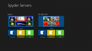
Main Screen


Home Screen

The main screen is the landing page for the application when opened, and displays all servers available on the network, each with a thumbnail sized live view and launch buttons to command keys, function keys, and still image pages.  The functionality is pretty straight forward, so I won’t list out what is there in more detail here, but there are a few things that I would really like to see go into a near future version of the application:

Planned Main Screen / General App Features

  • View of system health / user diagnostics (with launch button to a health screen)
  • Ability to select any of the buttons and open their associated pages in a new window, allowing multiple views to be displayed simultaneously.  This could be a big deal for multi-monitor users, and opens up more complex control and monitoring scenarios for even single monitor users.
  • Sources view / list, showing thumbnails and tally status.  Used in combination with the previous feature bullet, this could allow for drag-drop support onto the live view

Live View

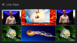
Spyder Client - Live View

This is effectively a display simulator view, designed to give a real-time view of the system’s PixelSpaces and layers using thumbnails pre-configured in Spyder.  Creating a full-featured simulator brings a number of complexities, and this control is very primitive by the standards of the simulator in Vista Advanced.  The live view control will undoubtedly be the benefactor or the majority of near future development work as a result, and to get the most bang for the buck I’ve re-used this same control to provide thumbnail visualizations for command keys and the thumbnail view on the main page.

Live View Features on Day One

  • Preview / Program PixelSpaces
  • Solid Color Borders with bezel luminance offsets
  • Thumbnails for PixelSpaces and Layers
  • Smooth motion views of layers and background transitions

Planned Live View Features

  • Full bitmap borders and shadows
  • PixelSpace Stackups (different view configurations for PixelSpaces)
  • Layer number indicators
  • Interactive control (layer pinch resize, reposition support)
  • Drag/Drop support for sources / stills

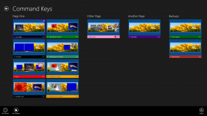
Command Keys View

Command Keys

The live thumbnail view within the command keys page is (in my humble opinion) the most interesting feature within the application.  This works extremely well at showing what-if scenarios for recalling relative command keys, but is very limited today by the general render capabilities of the live view control used to generate thumbnails.  I don’t think I can understate this; the renderer is pretty feature light and falls down quickly when showing more than the most basic of looks.  As stated previously though, this will gain all the development benefit of work applied to the live view, and so I think it’s only a matter of time for this to get flushed out.

Command Key Features on Day One

  • Displays user defined register colors for command keys
  • Groups buttons by existing user defined pages
  • Live generated preview of ‘Program’ (Cue 1) look for command key
  • Absolute / Relative Indicator
  • Preview / Program tally indicators

Planned Command Keys Features

  • PixelSpace stackup switching
  • Ability to turn off live view integration with thumbnail previews.  Not sure if anyone would actually want this feature – seems to me like once you have a feature like this you would never want to turn it off (would love your feedback)
  • Option for different button sizes to condense more command keys onto the screen
  • Pinch zoom support to jump between pages quickly
  • 320 pixel wide snap view support
  • Link to a full script grid view showing all command key cues with individual thumbnail previews.  I have a lot of thought into this, and will probably need a blog post all it’s own to describe further.

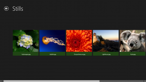
Stills View

Stills Viewer

The stills view came about early on as a side effect of needing to validate the image file processor / transport software, but was handy enough to keep around.  The Advanced client has the ability to obtain thumbnails from the server in a round about way (once you’ve seen them in the simulator they are cached locally in the ‘C:\Spyder\Images’ folder on your PC).

Stills View Features on Day One

  • View all Still images defined in the Still registers list on the Spyder server in thumbnail form
  • View a full screen view of all images by clicking a thumbnail
  • Ability to save image files locally via the app bar
  • Ability to share one or more selected images using the ‘Share’ charm in windows

Planned Stills View Features

  • Native shape file viewer (custom bitmap border shapes)
  • Native shape file creator, with the ability to simply draw a shape on screen and have it saved onto the Spyder server as a shape file.  This would have the ability to load an image into the background to be used as a stencil, and additionally preview the resulting shape at a number of different source aspect ratios.
  • Different thumbnail sizes to show more thumbnails on the screen at once

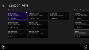
Function Keys View

Function Keys

I think the Function Keys view is off to a good start; it works (which helps), and it’s approach of showing a very brief text description of it’s execution action makes it easy to see what the button will do before you actually press it.  An interesting note about function keys:  the Spyder data model actually has support for custom register colors for function keys, but this is not brought forward into the Vista Advanced interface.  The Spyder client has support for displaying custom register colors as it does in the command keys view, and so this will auto-magically start working if this becomes implemented in Advanced in the future.

Function Key View Features on Day One

  • Display of Function key names
  • Display of the type of command key
  • Short text describing the action which will be performed when the key is executed (limited to one line of text, may be clipped depending on things like the number of layers affected)

Planned Function Key View Features

  • A pseudo-tally feature which would evaluate the state of the system and show a red tally indicator if the function key appeared to be in it’s executed state.  An assign source function key, for example, would show a program tally indicator if it’s associated source was already assigned to it’s target layer(s)
  • Relative layer recall support.  Function keys with relative layer/device assignments require the layer/device IDs to be specified at the time of recall, and currently there is no way to provide these when executing a relative function key from the Spyder client.
  • Option for a more compact view of buttons to display more function keys on the screen at once
  • Pinch zoom to quickly navigate between pages

Again, the planned features are on my wish list based on what I think would be great additions.  It’s entirely possible that I’m missing the boat on functionality that I’m just not thinking about, and if you think that’s the case then I’d like to hear from you.  Please leave your comments on this post, and in general let me know what you think of the app.

In a future post I’ll talk about the back-end development, project management, and source control technologies, and possible future directions for the platform.


Vista Advanced broken (and fixed) when running high DPI displays

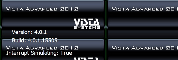
I recently became the proud owner of a Microsoft Surface PRO device, and was shocked to see that our main software application Vista Advanced looked absolutely horrible!  It felt like half of the UI was tiny, and the other half was massive in size.  The Splash screen graphic was even bad, having been drawn in a tiled display.  Take a look at this first-run / out-of-box experience on the surface running the latest release (4.0.1 at the time of this writing):

Splash screen background image wrapping

Splash screen background image wrapping

Oversized controls and UI elements make the app usability pretty rough

Oversized controls and UI elements make the app usability pretty rough

The Problem

The problem, it turns out, has to do with the application’s UI frameworks detecting the selected resize mode for the OS (set to 150% scale by default on high DPI devices like the Surface PRO), and scales up the bitmaps and fonts accordingly.  The really annoying part is that only some of the UI elements are affected by this, and this is due to a combination of different technologies and control libraries being used together to put Advanced together.

The Workaround (read: Hack)

There is a work-around to allow existing versions of Vista Advanced software to look normal on your high DPI device, and the way to do this is to open display resolution in control panel and look for the link that says ‘Make text and other items larger or smaller’.  That link will bring you to the dialog below, and from this dialog set the size of all items to 100% (Smaller).  This affects the entire OS, and has the additional requirement of needing you to log out and back in before the setting will take effect.   This is certainly far from ideal, but in a pinch it’ll at least get you by.

Use display settings to change the default size of items to 100%

Use display settings to change the default size of items to 100%

The Real Fix

Modification to AssemblyInfo.cs to disable DPI awareness

Modification to AssemblyInfo.cs to disable DPI awareness

Luckily there is a simple software fix for this problem that we were able to put in place. Inserting the DisableDpiAwareness attribute at the main application’s assembly level will disable the DPI scaling that happens on these high DPI devices, causing our application to render the same size on all computers.  Setting this attribute immediately brings the application back into it’s normal look and feel:

Normal looking splash screen after setting DisableDpiAwareness

Normal looking splash screen after setting DisableDpiAwareness

Normal Advanced application look after setting DisableDpiAwareness attribute

Normal Advanced application look after setting DisableDpiAwareness attribute

Now with this fix, you can see Advanced looks as one might expect it to look again, and without the user having to make any screen resolution hacks to do it.  You’ll see this fix in the next beta version of software (0.55.8), which will roll into version 4.0.2 for those of you who wait for release builds only.

Simple Spyder Preset Recall App for Windows 7 and 8

Back at NAB this year, Vista used a Microsoft Surface PRO device as a free-standing touch screen running a custom application to recall Spyder command keys.  A number of people asked about obtaining a copy of this interface during the show, citing it’s ease of use and simple functionality as a common use case that can be found across several environments.  I worked on this application in my free time leading up to the show, and as it stands this isn’t something that will be formally productized.  It’s a great application for what it does, and as such, I’m making this application available here for those who want it.

Quick screenshot of the preset recall app in action

Quick screenshot of the preset recall app in action

Now for the quick description:  this is a full-screen desktop application which leverages the Windows 8 Metro design philosophy for a modern look.  The app auto-discovers Spyder servers on the network and allows them to be selected in a drop-down (top-right of the screen).  Upon selecting a server, it’s command key pages and associated command keys are displayed.  The command key buttons are greatly oversized, optimizing them for touch-screen scenarios.  A single press of these buttons will recall the program cue of it’s associated command key, and active command key buttons will be displayed in red (take a look at the screenshot above).

If you have any questions or issues getting running, feel free to post a message on the blog here.  It takes zero configuration to get running (other than getting your client PC on the same subnet as a Spyder), and as of this writing has no known issues.  Give it a spin, enjoy, and let me know what you think!

Download the Spyder Preset Recall Application Now

Note:  This application requires the installation of the Microsoft .Net 4.5 Framework

Bitmap Borders and Shadows: Part 2 of n

In the first part of this series of posts I discussed how to use the bitmap border / shadow feature on Spyder X20 and how it works under the hood.  In this post, I’m going to discuss the process for creating custom shapes and getting them loaded into the X20 video processor.  You might want to create custom shapes for any number of reasons, a common one being for corporate logos.  Below are a few examples of custom shapes I’ve generated for the sales team for various demos over time.

CNN_Logo 
DVD player video cut into CNN logo
Shards 
Another DVD player cut into shards

So How is a Shape Defined?

The bitmap border / shadow engine uses a XAML (eXtensible Markup Language)  parser to convert a vector-based shape definition into the specially formatted raster-based image that is loaded to the video processor hardware.  The shape definition is imported into the system as a .shape file, which contains a single XAML PathGeometry definition. Below is the contents of a shape file defining one of the ‘shard’ shapes above:

<PathGeometry
   xmlns="https://schemas.microsoft.com/winfx/2006/xaml/presentation"
   xmlns:x="https://schemas.microsoft.com/winfx/2006/xaml"
    Figures="M 100,0L 62.75,0L 51.75,24.3333L 
     65.9166,24.3333L 66.25,45.3333L 75.75,30.5L
     5.5833,62.3333L 92.5833,75.5L  100,75.8333L 100,0 Z "/>

The real meat of the shape definition is defined in the Figures section of a PathGeometry object, which is written in a mini path syntax.  In practice you’ll be copying and pasting this data out of a tool like Microsoft Expression Design, but in case your curious there are several pages online that describe the XAML path mini-language (one here) that you can peruse in your free time if your curious to know more about how this syntax works.

Tools of the Trade

There are many tools capable of generating XAML output, but my personal preference is Microsoft’s Expression Design tool.  You can download a 60-day free trial of this tool on Microsoft’s site (here).

You’ll also want to have a basic template file that you can paste your custom shape data into.  You can pull this off my site here.

OK I have the Tools, now what?

The steps involved are easier to show than describe, and so I created a video walkthrough showing the process of creating a custom shape with Expression Design, saving it into a .shape file, and then finally importing that shape into Spyder using Vista Advanced.  The walkthrough moves pretty fast; if you have any questions just leave a comment on this blog post for me and I’ll try my best to help.


Summary

So hopefully this post has helped explain the basics of creating custom shapes for your X20 system.  In the next post I’ll spend some more time building custom shapes and logos in Expression Design, and I’ll cover a few tips and tricks I’ve found to make the process more efficient.