Tag Archives: Spyder

Building a Camera Tally Controller for Spyder in 2022

A whole 7 years ago I published a blog post and a couple YouTube videos showing a cool Tally (camera relay) system that anyone could make with a $35 Raspberry Pi device and $10 relay board. Back then this was running Windows on the Raspberry Pi 2 – a special stripped-down version of Windows called IoT Core that was designed to run on the Pi.

In seven years, a lot has changed. I started sprouting some gray hairs, Microsoft has all but abandoned Windows IoT Core on the Pi, .Net Core has become a mature way to deploy applications on Linux, and the Pi itself has had a powerful version 4 on the shelves for almost two years now. In this blog post, we’re going to modernize our prior approach and add some cool new features like a front panel display and a configuration/monitoring web interface.
Features and Overview

  • Works with Spyder 200 / 300 / X20 / X80 hardware
  • Works with every major release version of Spyder software
  • Supports different servers and rules per individual tally
  • Built-in web server for remote configuration and monitoring
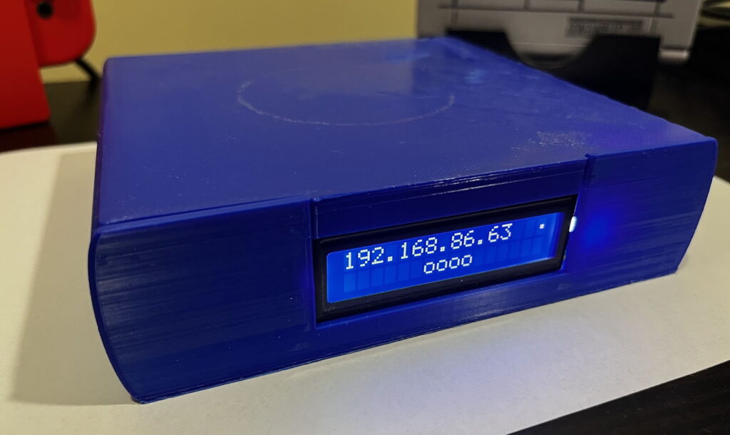
  • Front panel shows device IP and on/off tally icons for quick viewing of status

If you have a Spyder video processor of any generation, this device will work as a tally controller. For those wondering what tallies are, imagine a live show where multiple cameras are pointed at talent on a stage. Lights are usually physically positioned on top of the cameras and light up when a camera is ‘live’ to help the talent know which camera they should be looking at. The tally controller described here contains relays (electronically controlled contact closures) which open and close when specific sources are shown or hidden in windows on Spyder.

The video below walks through the device hardware and software, providing probably a better end-to-end overview than this blog post for those of us out there who prefer to consume video content.

Parts you Need

First off, you’re going to need to buy some parts. Here’s a list of what you need, some of which you may have around the house:

3D Printing a Chassis

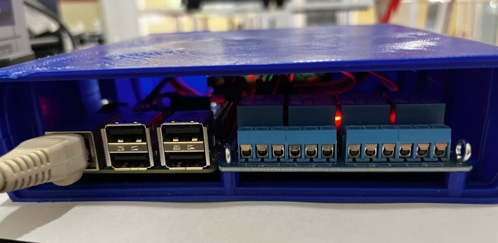
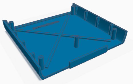
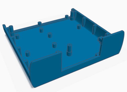
I used TinkerCad to design a simple chassis to hold a 4-relay board. You can copy and modify this design as you see fit, but for most folks you can simply download the 3D print STL files for the top and bottom pieces, and either print them yourself or send them off to a 3D printing service. If you watch the video from earlier in this blog post you’ll see the Raspberry Pi and the tally board are on the wrong sides of the chassis, and I’ve corrected this in the current design.

Chassis Top PieceChassis Bottom Piece
View in TinkerCadView in TinkerCad
3D Chassis Parts for Tally

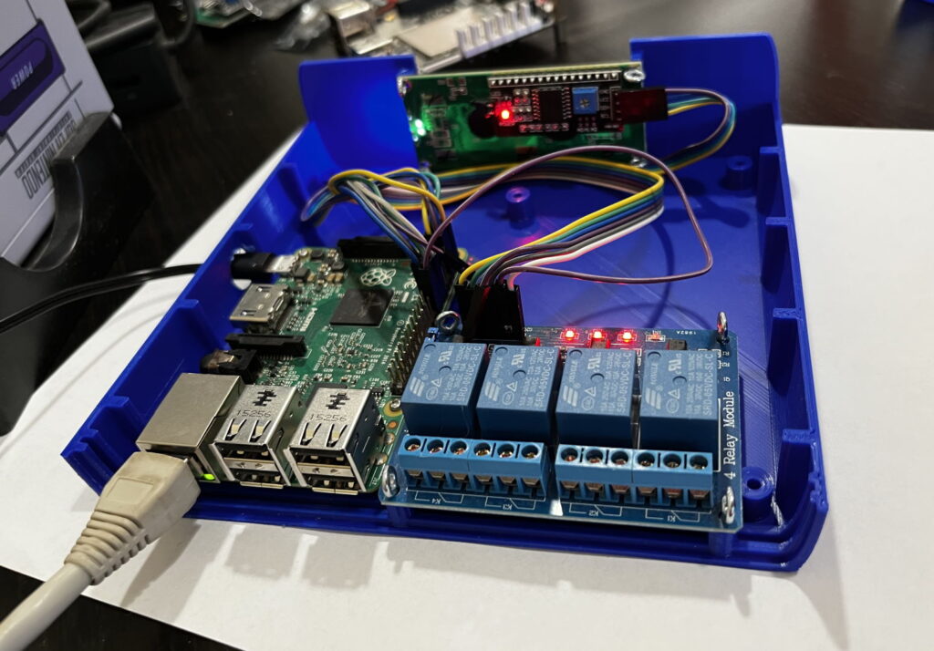
Building the unit is quite easy once you’ve acquired and printed the parts required. The open frame views in the video show off mounting the raspberry pi, tally board, and LCD front panel display in the chassis.

Wiring the pieces together

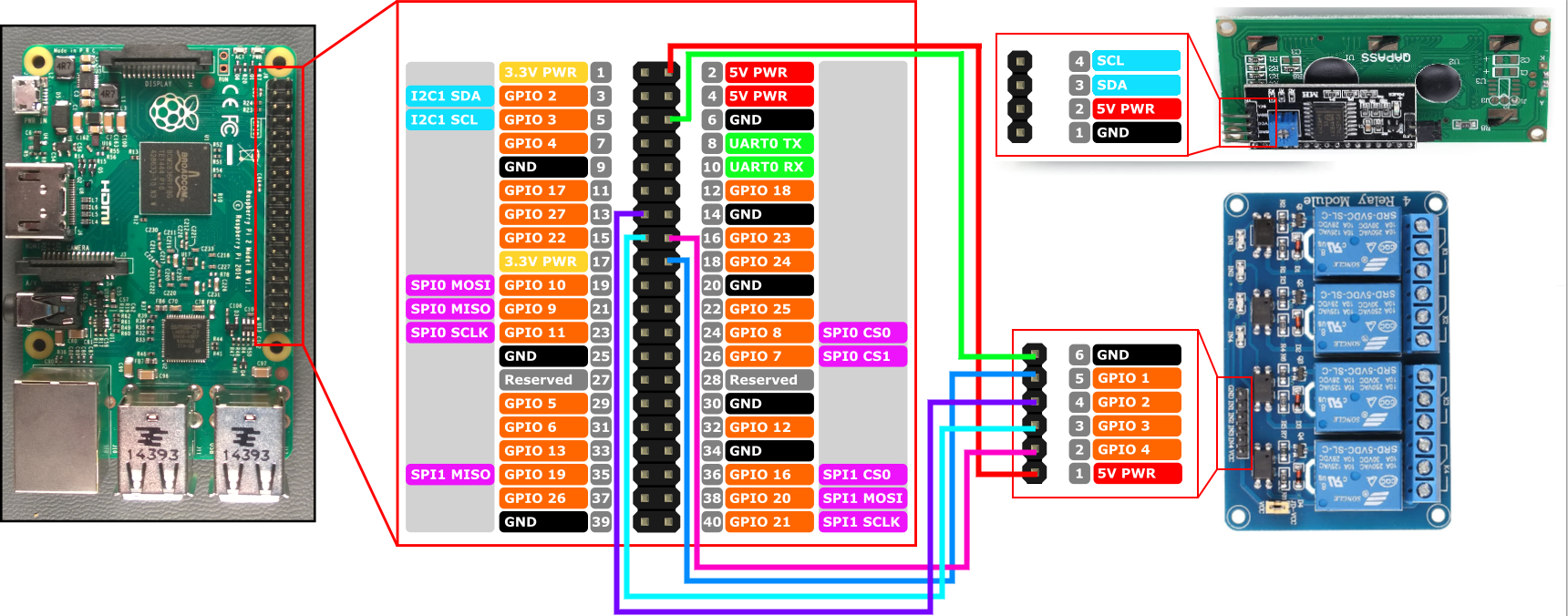
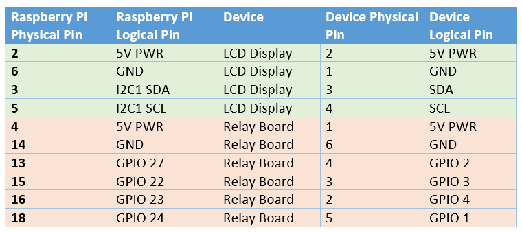
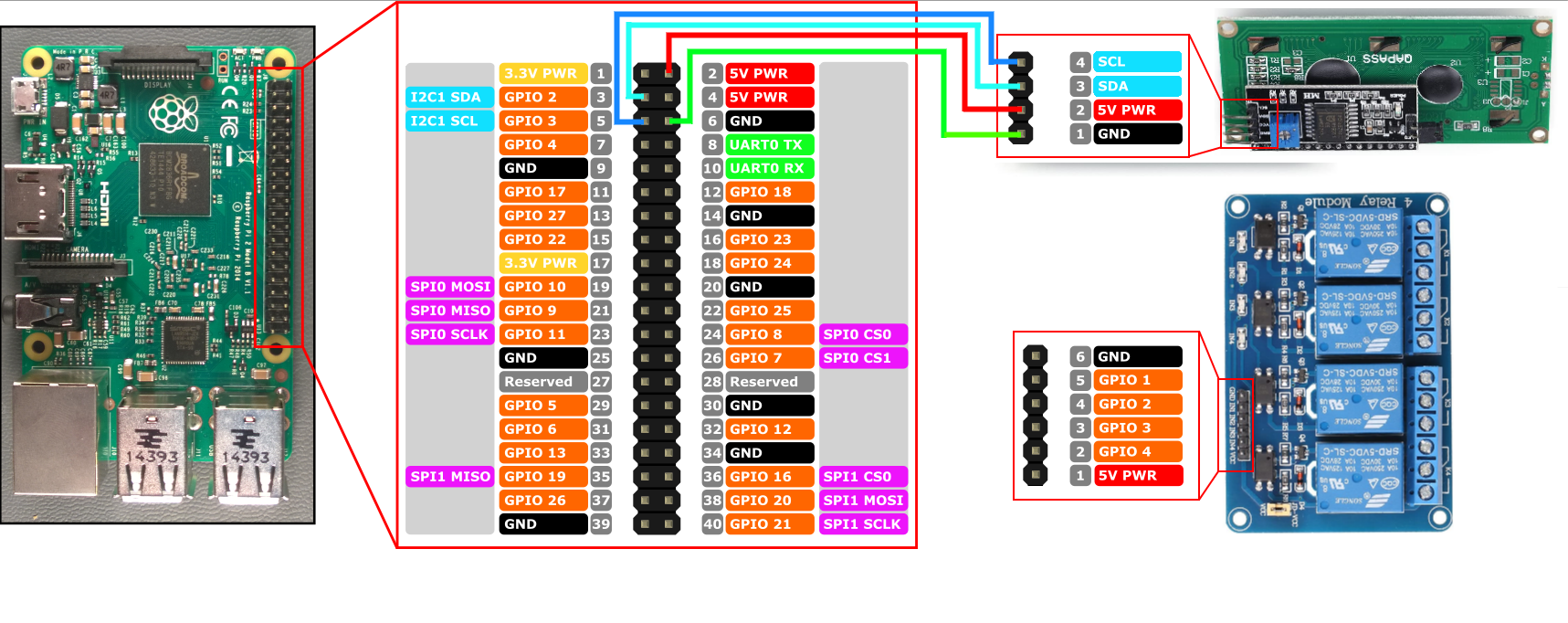
You can use simple breadboard style wiring connectors to save yourself from any kind of soldering, making the assembly a ‘Lego-like’ plug and play experience. The images below show the connections you’ll wire up from the Raspberry Pi to the LCD display and the relay board. If you’re creating a tally controller with more than the 4 relays shown, you’ll simply pick some more GPIO ports on the Pi for the additional connections (just be sure to write down which pins are connected to the relay pins for later configuration).

Spyder Tally wiring pinout
Wiring diagram for connecting Pi to the LCD display
Wiring diagram for connecting Pi to the Relay board

Installing the Pre-Built Raspberry Pi Software

Download SD Card Image for Raspberry Pi and/or release binaries here

Installing the pre-built software image for the Raspberry Pi is the easiest way to get going. You can download the SD card image directly from the Spyder Tally GitHub project’s releases page and use the official Raspberry Pi Imager tool to write that image file onto an SD card.

After writing the image file to the SD card, insert it into the Raspberry pi, connect an Ethernet (network) cable and power it up. It shouldn’t be necessary to connect a monitor to the Pi, but it does feel nice to keep an eye on it during the first boot where it will perform one-time tasks like expanding the file system to fill the SD card. That first boot will take several minutes, but eventually you should see the front panel light up and show the unit’s IP address.

Note that the software will wait for the network to become available before launching, and so you will not see anything until after the network is plugged in.

Installing Manually (Raspberry Pi or Other Devices)

If you’d like to use a device different than the Raspberry Pi, or if you want to build your own Raspberry Pi image for whatever reason, you’re in luck because it’s easy to do! The software may need some tweaking (particularly around hardware interface control) but should readily run on a wide variety of Linux devices including x86, x64, and ARM hardware with minimal tweaking.

The steps involved in creating your own disk image can be extrapolated from this README up on the project’s GitHub site.

One tweak I made when building the v1.0.0 SD card image – instead of installing the .Net Core framework on the device, I compiled the app as a ‘self-contained’ deployment. This kind of deployment bundles in all the .Net runtime pieces needed to run the application, and can both slim down the overall disk footprint and decouple the app from needing to be deployed on a target with a compatible .Net framework version. I like this approach and will likely continue this trend in future releases.

Summary

Spyder is an excellent product, and I’ve always been proud to have been a part of its history during my years at Vista / Christie Digital. Making accessory software and devices like this tablet controller still make me incredibly happy even years later. I hope you enjoy making your own as much as I enjoyed creating it. Let me know what cool environments you end up using it in!

If you run into any snags or have ideas for improvement on the project, the easiest way to communicate is to file issues up on the project’s official GitHub repository issue tracker. I do keep an eye out for comments and will try to reply as I can, but I tend to have a bad habit of not checking for comments for months at a time 🙂
ScreenMaster III 3216 Console

ScreenMaster III 3216 – Restoring a Classic – Part 1

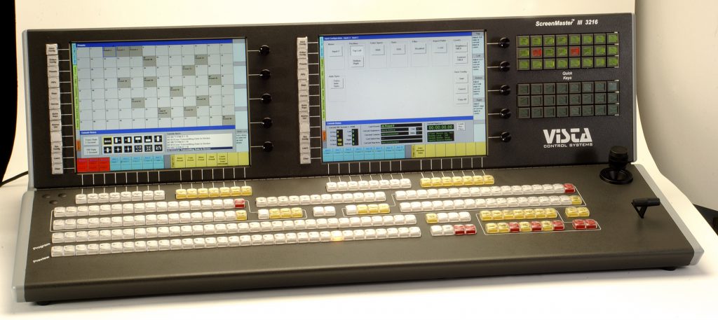
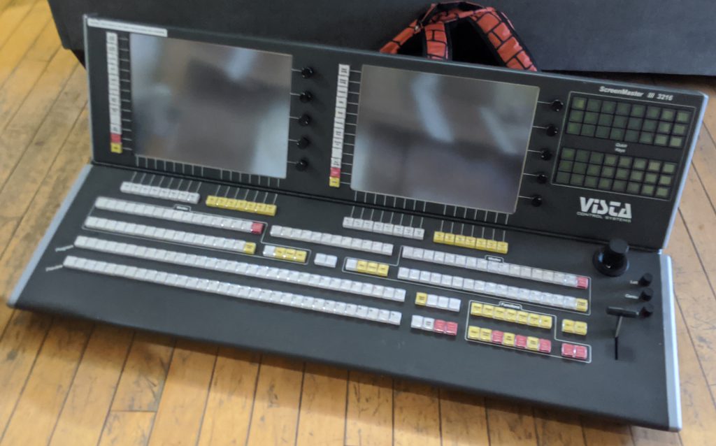
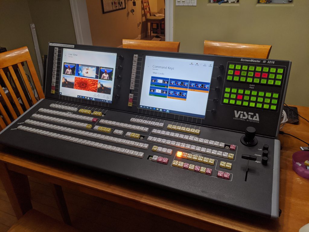
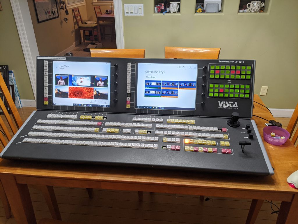
The ScreenMaster III 3216 and it’s half-sized little sibling the 1608 were some of my favorite consoles every made at Vista Control Systems (later renamed to Vista Systems and later acquired by Christie Digital). These were the first consoles to incorporate 15″ touch screen displays to compliment the massive button boards from prior console generations. This console, like others before it, were purpose built to control a combination of Folsom (now Barco) VFC-2200 scalers and either Extron, Pesa, or Sierra routing switchers. We’re talking analog video only here – this was the nineties after all, when 1080p video was king.

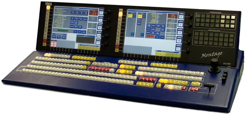
It’s worth a note that this console would be appear again in the future as the control surface for the Vista Montage video processor, painted in blue and re-dubbed as the Montage SC-3200 console. This stuff is all but lost in time, even on the internet these days, and so I’ve included a picture below for full historic reference.

Let’s talk about this got started

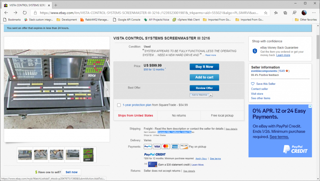
Let’s talk about eBay. eBay is a great place to get great deals, and is a great place to troll late nights when you can’t sleep to find stuff you didn’t know you needed (and probably don’t need). One night I happen to be aimlessly looking around the internet, and somehow I made it to this posting on eBay:

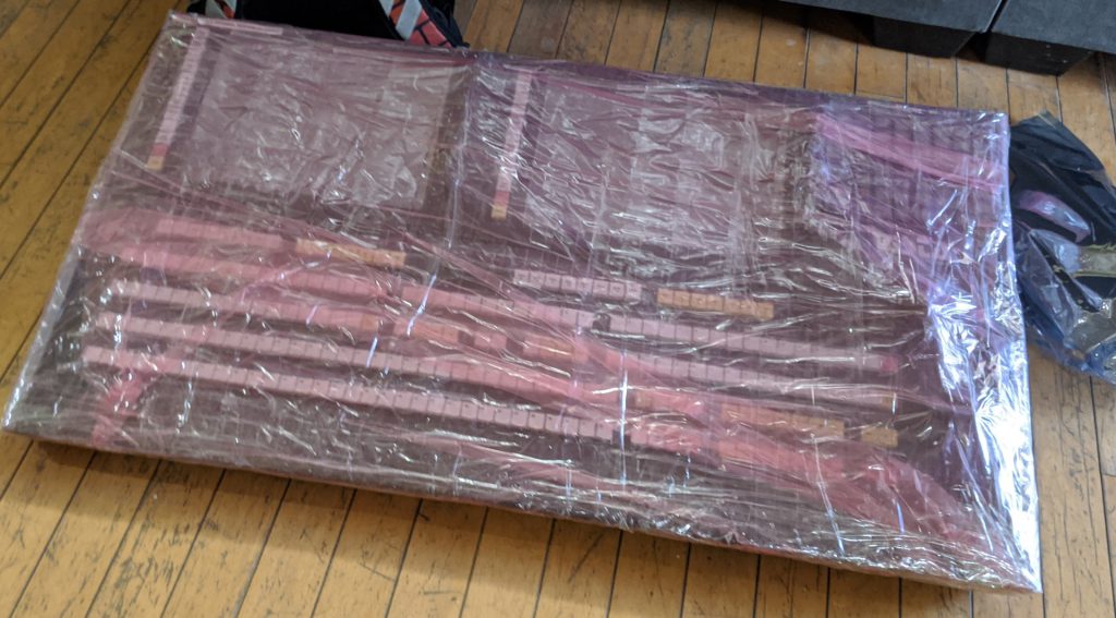
This picture of the console immediately gave me ‘the feels’, as it has solid sentimental value. I remember shipping the first of these consoles, sometime back in the nineties. We had a problem with a driver for an internal USB network adapter, and it was causing the console to bluescreen. We weren’t sure it was fixed, but I ‘thought’ I had resolved the issue with an updated driver. We got the console in it’s case and brought it to the back door. After talking a bit about this bluescreen, Jeff Wilson and I opened the console up and made sure it booted successfully five times. As long as it could boot five times in a row, then we’d ship it. Good news – that was the day unit #1 shipped.

<rant>Just to touch briefly on that last point – this was a time when Windows was considered to be generally unstable, and we caught a lot of flack from rental and staging customers (and competitors). Here we were though, shipping a device with Windows (NT Embedded I vaguely recall) and asking customers to entrust their high-dollar live events on it. Software bugs aside, I think this ask proved to be a reasonable one and these consoles were way ahead of their time (my opinion). </rant>

So this console on eBay had an asking price of $599, and I sent an offer for $299 which was accepted. I don’t remember the real figure, but I think this console cost around $45,000 new. From the pictures I could see some button-board activity and a boot failure, and so I knew that (1) the embedded part of the console was alive and (2) the PC was ‘alive’ and the Compact Flash card we used for the hard drive had likely failed. After some back-and-forth on the shipping, we decided to drop the shipping case to avoid going freight, and all-in I think I was down $500.

The arrival

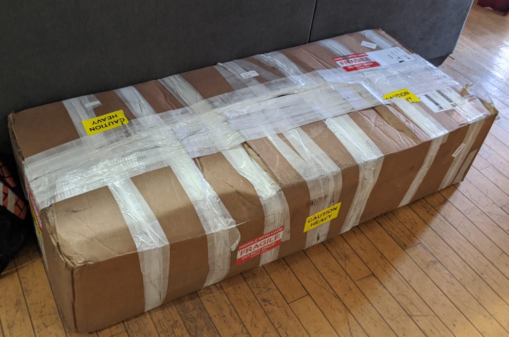
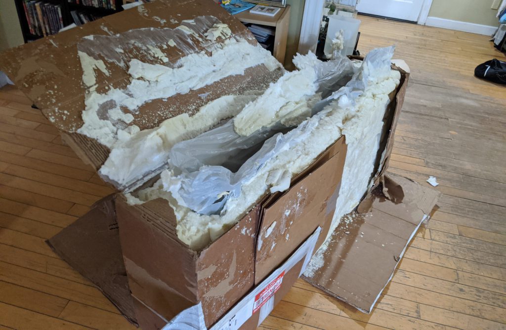
It took about a week for my console to arrive, and it showed up packed tight with instant-foam in a box that must have had a roll of fiber tape for additional support. It took a solid hour to practically chisel the console out of this foam tomb, but it shipped in pristine condition so I can’t complain.

After getting the console freed from it’s shipping cocoon, I gave it a good look over and powered it up. The screen showed the same hard drive failure message that I saw on the eBay post. The quick-keys (the top-right green button array) showed diagnostic counters that I was able to use to verify that the buttons, joystick, T-bar, and rotary encoders were all functional (minus a few burnt-out incandescent switch lamps). So far so good. Next up is to take inventory of the computer hardware and try to get it working again, but before we move on go ahead and take a hard look at that good-looking piece of hardware 🙂 .
Console internals

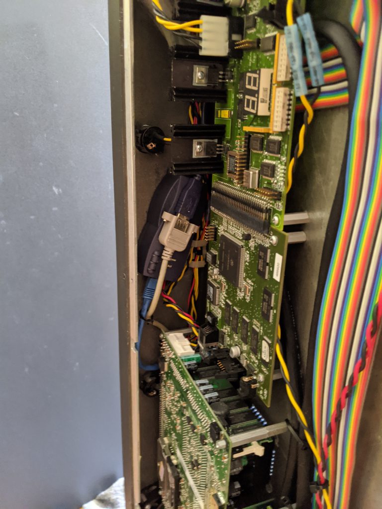
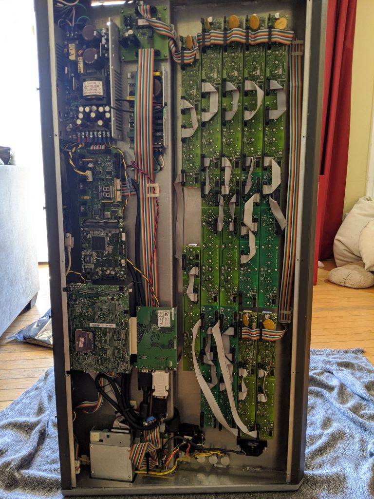
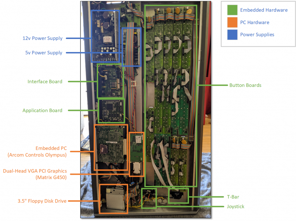
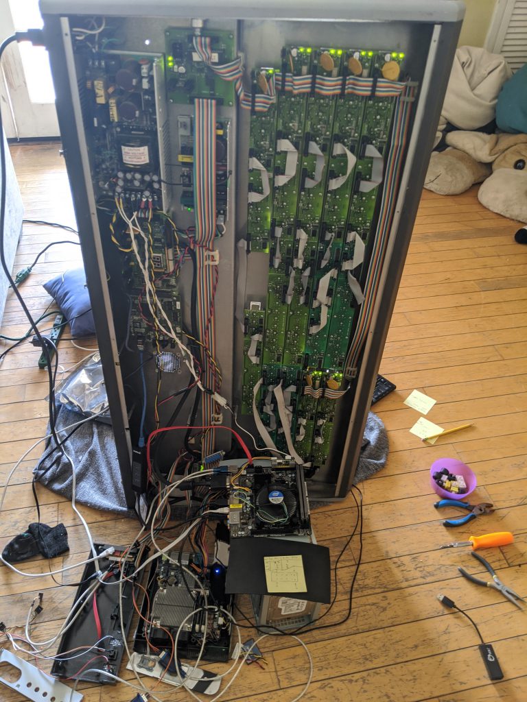
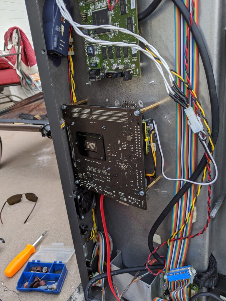
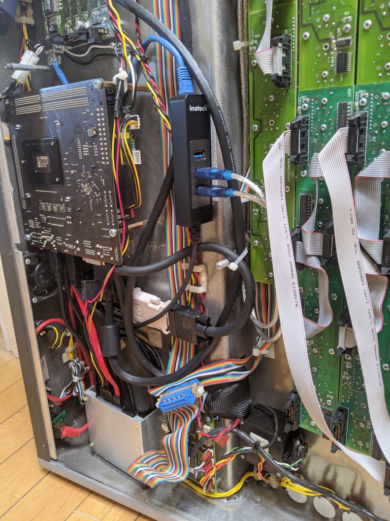
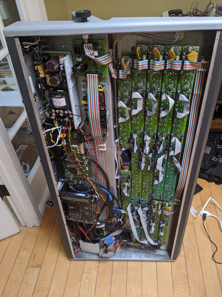
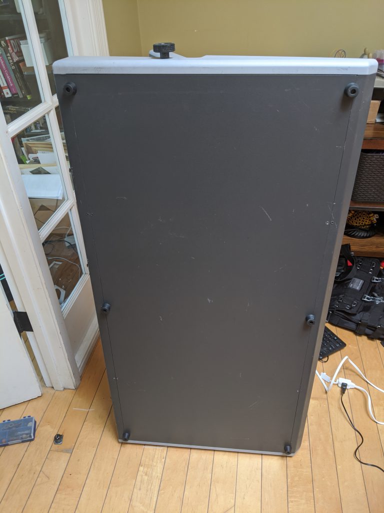
When you open the bottom of this console, you immediately see that there is a LOT going on. Luckily, when we look closely at the internals of the console there are two main subsystems – the embedded computer (PC) and the physical control interface (buttons / T-Bar / Joystick) subsystem. The picture below shows the console on it’s side with the bottom removed.

The application board is the main embedded component which houses the programming required to read and write the physical hardware. Luckily for us, the interface between the embedded computer and this application board is Ethernet. It’s difficult to see in the pictures, but there is an Ethernet crossover cable between a second Ethernet port on the SBC and the application board. This is great, because it means that we can upgrade the embedded computer without worrying about obscure hardware interface dependencies.

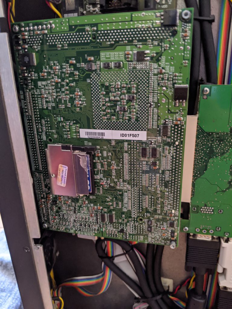
Before we move on to replacing the embedding computer, let’s take a second to talk about the embedded computer that came with the console. This was an EBX form factor computer called the ‘Olympus’ and was manufactured by Arcom Controls (datasheet here). This was a 1.0 Ghz Celeron processor and 128MB of RAM. The hard drive was provided with a 128MB Compact Flash card, which has limited read/write cycles and almost certainly explains why the console eventually stopped working. I did try jump-starting the console with a new Compact Flash module, but the SBC was so old that it felt that even if I could run a modern operating system on it (unlikely) that it would be terribly slow. It was also sporting a 3.5″ floppy disk drive, for those of you who remember what that even is, and I knew that needed to be brought into the modern age as well. With that back-story out of the way, let’s get to upgrading.

Upgrading the Embedded Computer Hardware

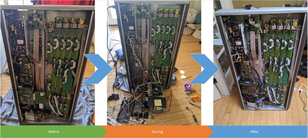
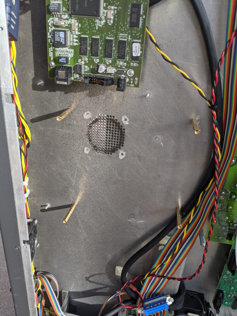
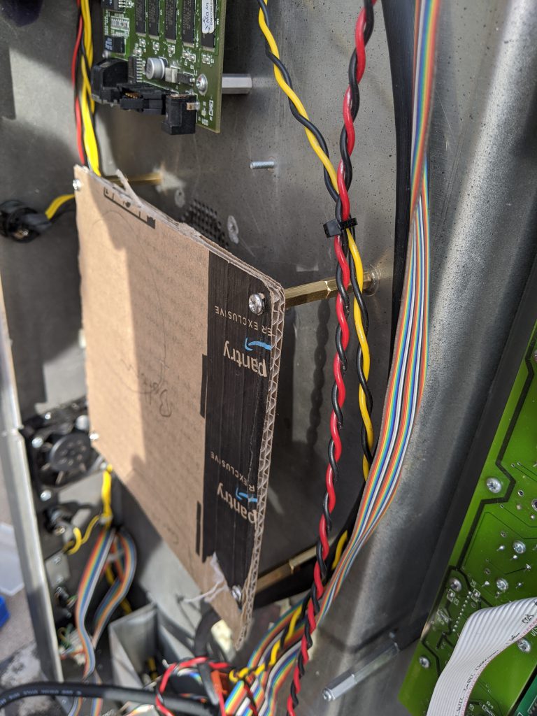
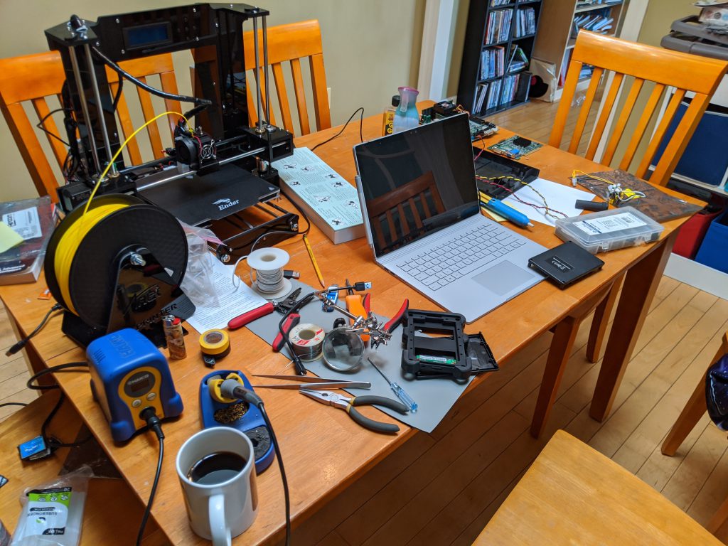
Full disclosure here – this console sat on it’s side in my living room for several weeks, and I’d give it occasional blocks of evening and weekend time. This wasn’t particularly hard, but there were some time-consuming parts of the effort that I’ll bullet point rather than writing a book about:

  • Removed the prior EBX form-factor PC board and graphics adapter
  • Removed the existing floppy disk drive
  • Drilled holes in the chassis to fit a new Mini-ITX form factor PC
  • Bought a +12V to ATX power adapter module to power the new SBC
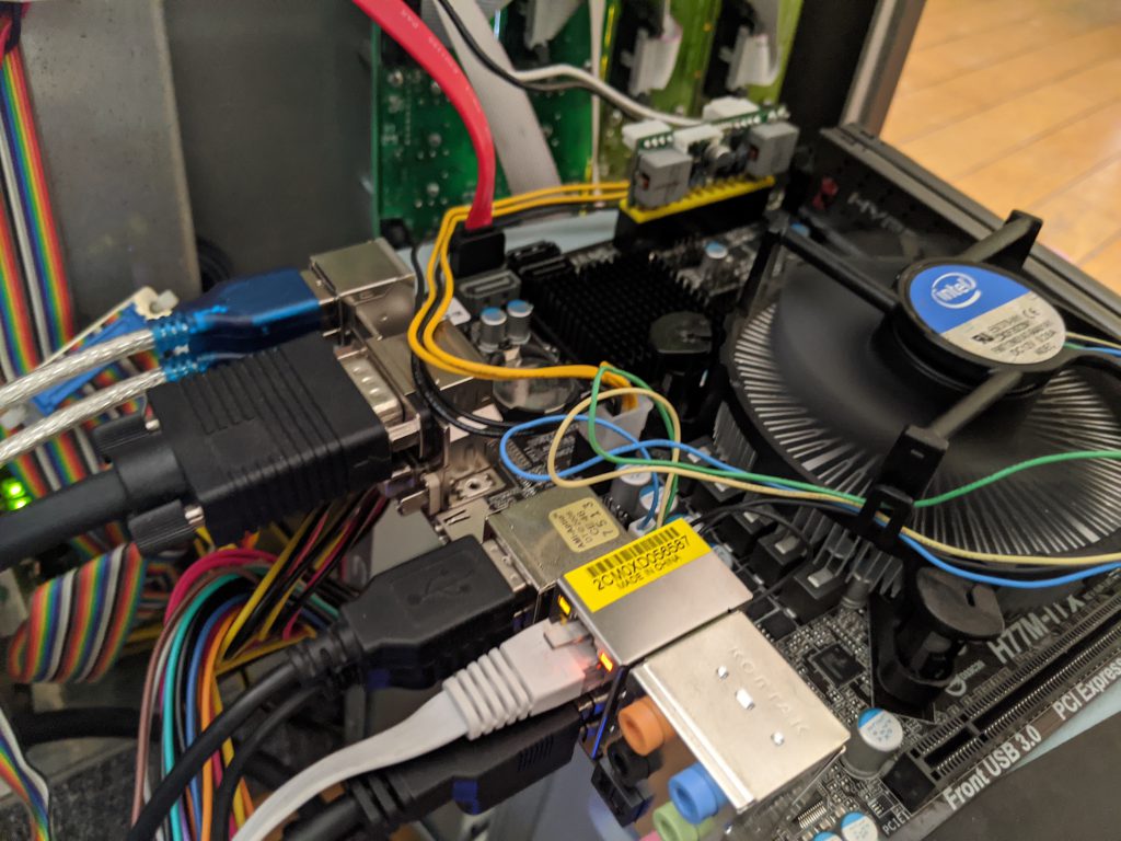
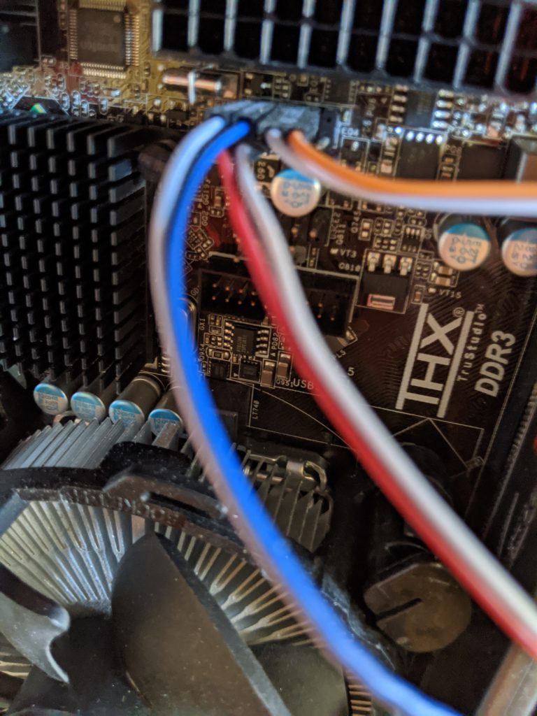
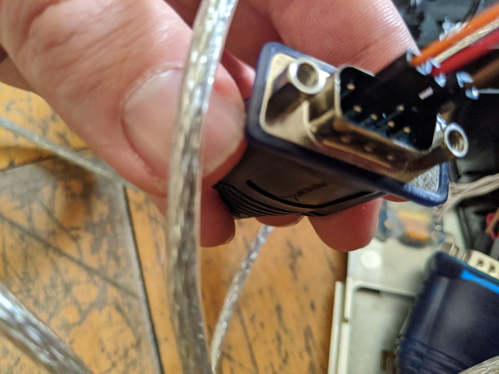
  • Added two USB to RS-232 cables to drive the touch screens
  • Added a USB to Analog adapter to drive the second touch screen (the SBC had one VGA port I was able to use as well)
  • Replaced the Neutrik Ethernet connector running to the back of the console with a new one
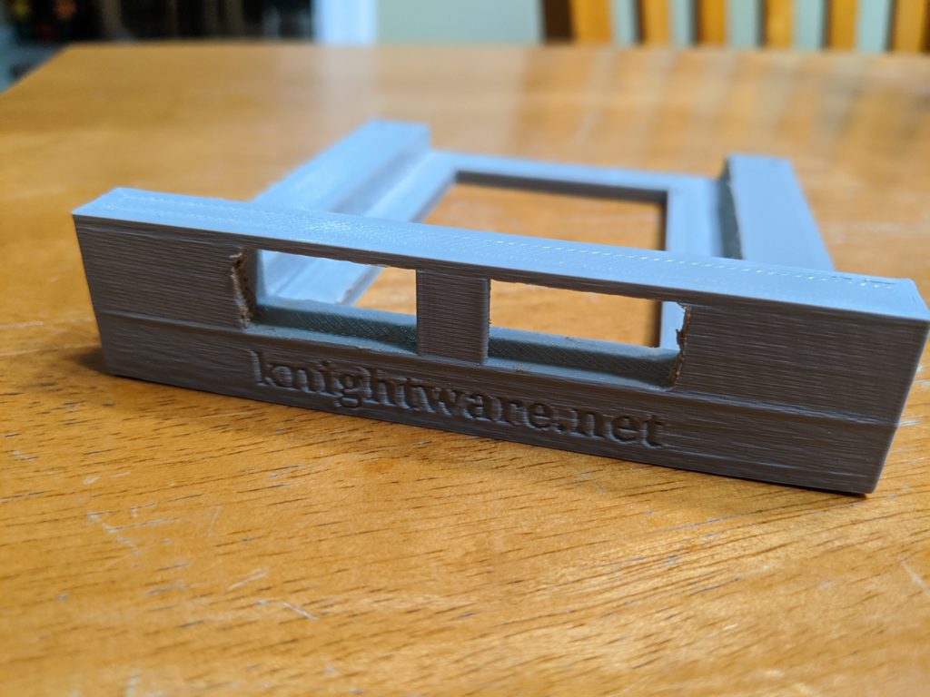
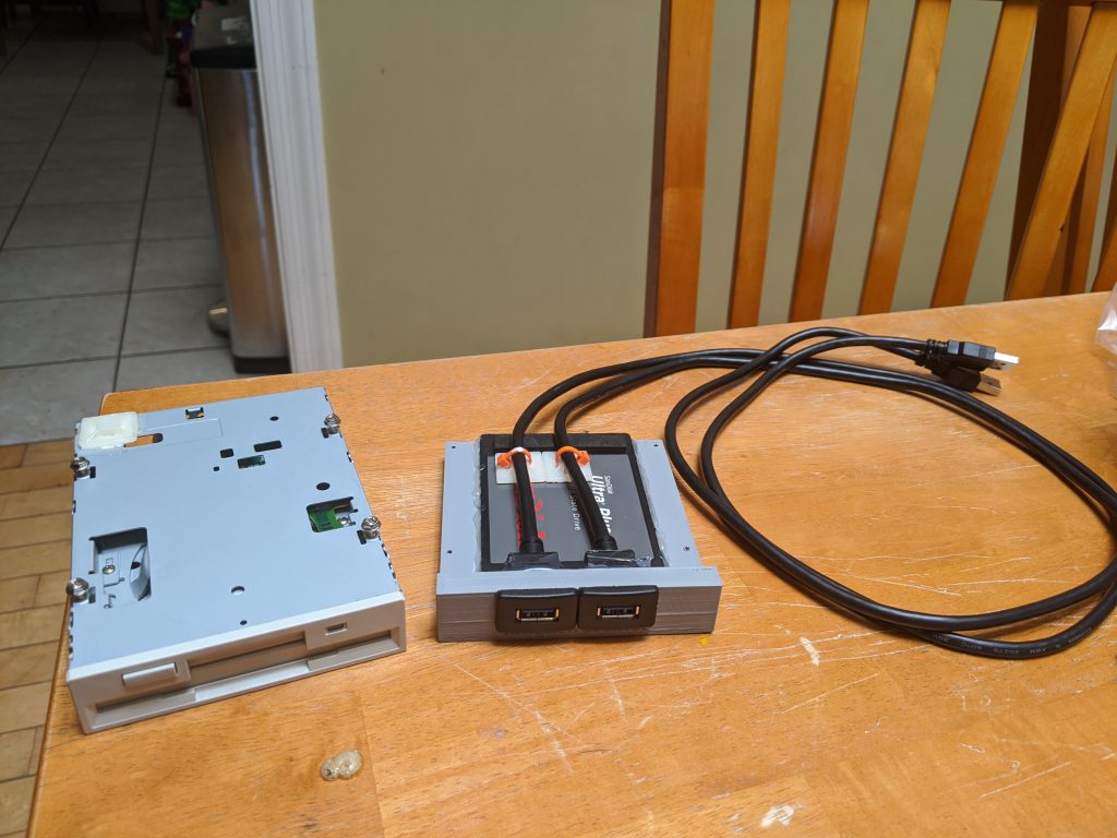
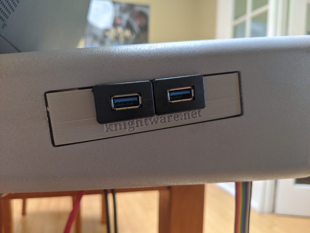
  • Modeled and 3D Printed a custom bracket to hold a new Solid State hard disk and expose 2x USB 3.0 ports to fit in the old floppy disk drive spot.

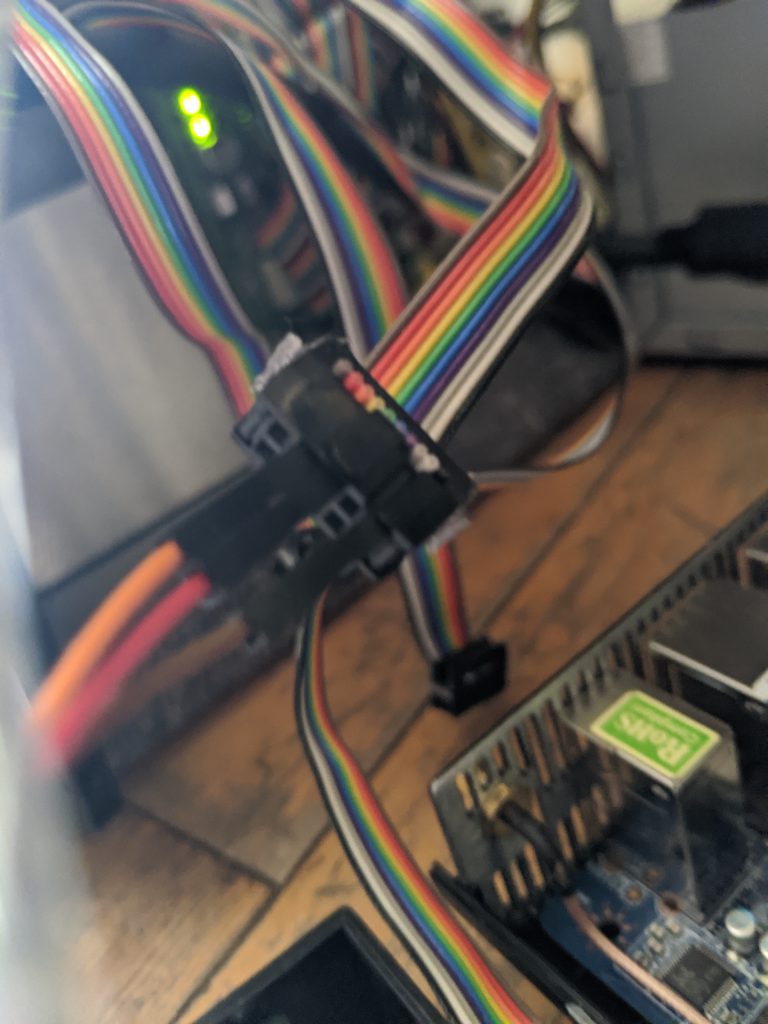
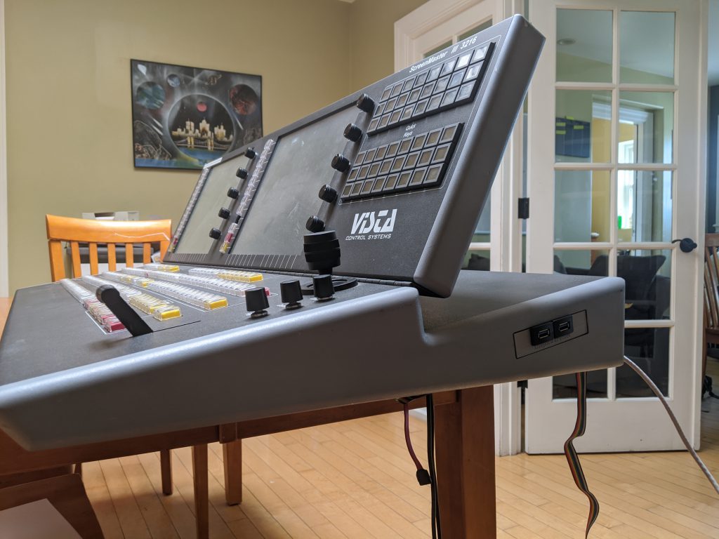
The mounting and retro-fitting of the new SBC and parts was a pain, but I’m pretty happy with how it came out. This thing feels like it could travel and be as reliable as the original console was. I am particularly proud of the 3D printed module that I made to hold the hard drive and expose a couple USB ports, and you can see this along with a bunch of other build pictures below

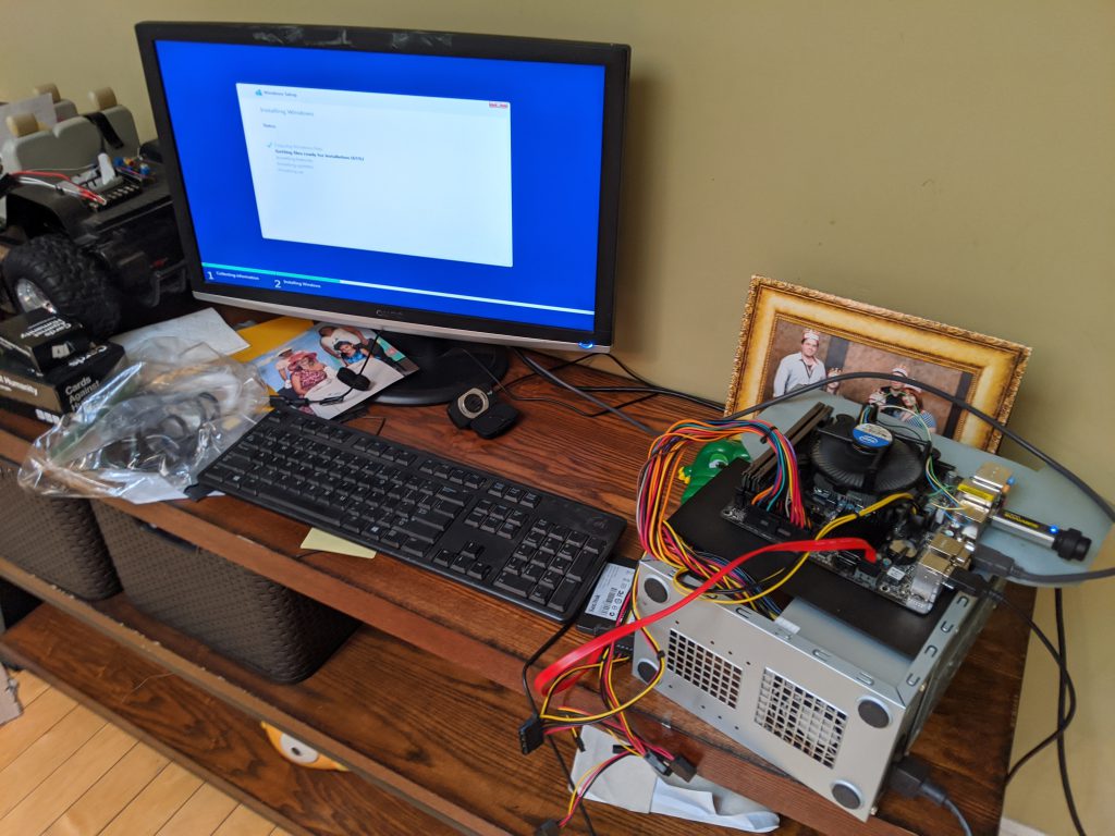
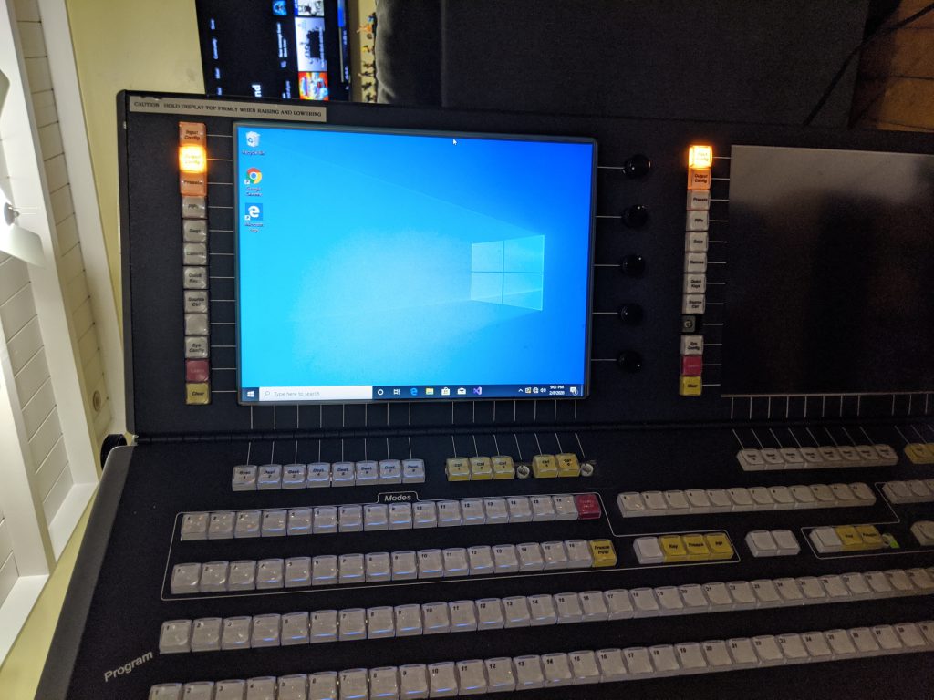
After the aforementioned evenings and weekends spanning may weeks, the hardware for the console was done. It was now sporting an Intel i7 processor with 16GB RAM and a 512GB solid state disk, and was running quite nicely. I did sneak in a picture of installing Windows on the replacement Embedded PC / Single Board Computer (SBC), but I’ve saved this for the last section of this post.

Let’s put Windows 10 on this thing

A modern console needs a modern operating system. I actually considered installing Ubuntu Linux for the fun factor, however ultimately I decided to install Windows 10 Pro. It’s less ’embedded’, but it allows for wider flexibility for software to run (including Vista Advanced / Spyder Studio / Spyder Client software).

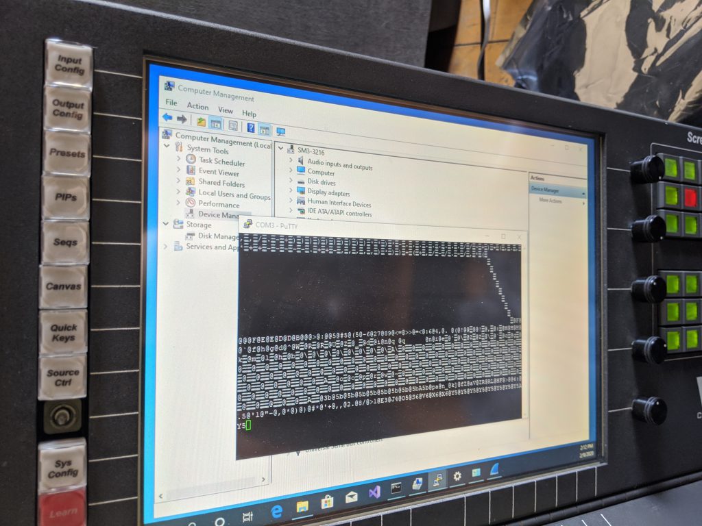
One wrinkle that I did run into was around the touch screens. They have RS-232 serial controllers, and the native 3M driver didn’t work. I remember running into this with my Car computer touch screen (same hardware), and so I knew I needed to pony up and buy a license for a software called touch-base that makes the touch controllers work with Windows 10. Related note – the screens for the console are each 1024×768 resolution and VGA, and if I were braver I would crack open the top and try to replace them with some newer displays. Maybe someday.

Big reveal time

I don’t need a lot of words for this – I’ll let the pictures of the console working speak for themselves. For those curious, the pretty looking Spyder control software is the Spyder Client application that is available on the Windows 8/10 Store.

So where are we, and what’s next?

So we have a large powerful hardware console alive and well, and we have a working PC operating system on it. Probably a way over-powered PC in there hardware spec-wise, but we still don’t know what we’ll do with it so hard to say. By the time I write this, the console has actually been sitting in my dining room for the past two months. I’ve already done some development and created a software interface to integrate the hardware with the PC, but I’ll save that for a future blog post.

In the next post, I’ll talk about how the PC-to-embedded hardware interface works, and we’ll probably have a simple app to show take a look at. I expect the next post will be a bit shorter – this one was a monster and it feels like it just skims the surface. With that, thank you for reading and see you next time!

Building a Camera Tally Controller for Spyder

Over this past weekend I set out to create a camera tally device for the Spyder video processor.  Specifically, I wanted to try to use my relatively new Raspberry Pi 2 board running the Windows 10 IoT Core operating system to make something useful.  If you’ve read through my older blog posts, you’ve likely noticed that the Spyder is still my go-to target platform for playing with new technologies.  Let’s face it – when you’re playing with shiny new toys, it helps to mate it up with something you know very well so you don’t feel completely lost.  Before I get into the details, check out this brief video showing a working tally controller in action:

The whole process of building this device was simply fantastic.  The barrier to entry for people making hardware devices has gotten incredibly low over the past couple years, both from a cost and ease of development perspective.  The whole build process was very quick, and I had such a great time with it that I went ahead and put together a full 30 minute hardware and software video walk-thru for the project (more on this below).

Getting Started Making your own

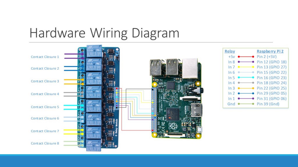
To get started making your own, here are a couple links for the main hardware used on this project, as well as the wiring diagram for your reference.

Raspberry Pi 2 Kit ($70):  Amazon Link
8-Channel Relay Board ($9):  Amazon Link

Tally Wiring Diagram

Hardware Wiring Diagram for our Tally Controller

Links to the full source code, documentation resources, and a full YouTube walk-thru video are below.  This video has a ton of valuable information in there, covering the hardware specifics, Spyder implementation details, and the full process of creating our software application.  This is the first time I’ve gone through and made something this elaborate (and narrated the video), and I’ll be very interested to know what you think of it (so leave me a comment below if you’re so inclined).

GitHub Project (Source Code and Documentation):  Click Here

Next Steps

The tally controller we’ve created is certainly functional. but in it’s initial form the server IP address and tally source lists are hard-coded.  In the next stage of this project, we’re going to build a desktop application that can connect to the device remotely over the network and view/configure these properties.  We’ll also explore creating a user interface to run on the Pi’s HDMI output, which could be useful for monitoring and troubleshooting the device.

Until next time, take a look through those walk-thru video and the resources in the Github repository, and try to make one yourself.  I hope you enjoy going through this content as much as I enjoyed making it.

Bitmap Borders and Shadows: Part 2 of n

In the first part of this series of posts I discussed how to use the bitmap border / shadow feature on Spyder X20 and how it works under the hood.  In this post, I’m going to discuss the process for creating custom shapes and getting them loaded into the X20 video processor.  You might want to create custom shapes for any number of reasons, a common one being for corporate logos.  Below are a few examples of custom shapes I’ve generated for the sales team for various demos over time.

CNN_Logo 
DVD player video cut into CNN logo
Shards 
Another DVD player cut into shards

So How is a Shape Defined?

The bitmap border / shadow engine uses a XAML (eXtensible Markup Language)  parser to convert a vector-based shape definition into the specially formatted raster-based image that is loaded to the video processor hardware.  The shape definition is imported into the system as a .shape file, which contains a single XAML PathGeometry definition. Below is the contents of a shape file defining one of the ‘shard’ shapes above:

<PathGeometry
   xmlns="https://schemas.microsoft.com/winfx/2006/xaml/presentation"
   xmlns:x="https://schemas.microsoft.com/winfx/2006/xaml"
    Figures="M 100,0L 62.75,0L 51.75,24.3333L 
     65.9166,24.3333L 66.25,45.3333L 75.75,30.5L
     5.5833,62.3333L 92.5833,75.5L  100,75.8333L 100,0 Z "/>

The real meat of the shape definition is defined in the Figures section of a PathGeometry object, which is written in a mini path syntax.  In practice you’ll be copying and pasting this data out of a tool like Microsoft Expression Design, but in case your curious there are several pages online that describe the XAML path mini-language (one here) that you can peruse in your free time if your curious to know more about how this syntax works.

Tools of the Trade

There are many tools capable of generating XAML output, but my personal preference is Microsoft’s Expression Design tool.  You can download a 60-day free trial of this tool on Microsoft’s site (here).

You’ll also want to have a basic template file that you can paste your custom shape data into.  You can pull this off my site here.

OK I have the Tools, now what?

The steps involved are easier to show than describe, and so I created a video walkthrough showing the process of creating a custom shape with Expression Design, saving it into a .shape file, and then finally importing that shape into Spyder using Vista Advanced.  The walkthrough moves pretty fast; if you have any questions just leave a comment on this blog post for me and I’ll try my best to help.


Summary

So hopefully this post has helped explain the basics of creating custom shapes for your X20 system.  In the next post I’ll spend some more time building custom shapes and logos in Expression Design, and I’ll cover a few tips and tricks I’ve found to make the process more efficient.

Bitmap Borders and Shadows: Part 1 of n

In this next series of posts, I’m going to discuss the bitmap borders and shadows (BBS) feature that first appeared in Vista Advanced 3.5.0.  If you haven’t played with them yet, you owe it to yourself to do so. 

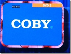
This first blog post will discuss how (and when) you can use the feature, how it works under the covers, and how to get the best possible performance from it.  If you have no idea what the bitmap borders and shadows feature is, take a look at the action shot below.

358

The image above shows two related features, bitmap borders and shadows and window titling.  I’m going to skip over titling for this post, and concentrate only on the bitmap border / shadow feature.

What Can I do With Bitmap Borders?

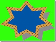
Bitmap borders goes beyond the traditional supported borders to enable custom shapes and fills to be defined.  Shadows applied will keep the same shape as the bitmap border, and can even have a color other than black defined (not shown).

one layer

Features Shown:

  1. Non-Rectangular window (rounded edges in this example)
  2. Image file used as border texture
  3. Shadow shape that matches the border shape

The Spyder software comes with about a dozen border shapes that you can use, as well as a number of images that can be used to texture the border.  Of course you can create and use custom shapes and fill images, which I’ll be discussing in detail in the next blog post.

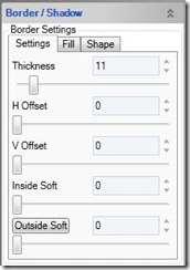
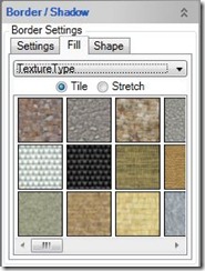
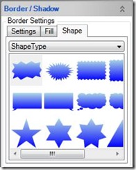
The KeyFrame property panel contains handles for all of the available bitmap border and shadow adjustments, and I’ve included a few screenshots of the most interesting ones below.  Using them is pretty self explanatory, and so I won’t bother going through them exhaustively.

border settings border texture border shape
General Settings Border Texture Border Shape


So How Does It Work?

Under the covers, the border / shadow settings selected are used to generate a specially formatted image at a size relative to the input video resolution, which gets loaded once into the target layer where it is in turn merged with the video each frame. The Images below show this process.

Example - Source Video Frame Buffer (2048×1200)

In this frame buffer, the active video is repositioned so that it will fit correctly when merged with the border image loaded.  These offsets are programmed by the server as part of the image loading process

Example - Border Bitmap  Buffer (2048×1200)

This buffer stores the generated image which will be merged with the video.  Special bit values are encoded into the image to specify what area of the image should be mixed with the video and which area should be mixed with the VI.

Example - Both Resulting Image

Once the image is loaded, the hardware in the X20 layer will perform the video cutout and merge the image with the border on a frame-by-frame basis.

Note that the image sequence above makes a point to call out the frame buffer sizes in the layer hardware; a size of 2048×1200.  This is important because the generated image file previously mentioned needs to fit within these dimensions.  Since the image file must be loaded relative to the input video resolution, there may not be enough ‘free’ frame buffer space to generate the desired effect. 

In cases where there isn’t enough space to fit the requested bitmap border / shadow settings, the server will automatically scale back the border offset and then the border thickness until the image fits.

Also note that the image files generated can be relatively large, and in almost all cases you really need to be running a still server to ensure a good experience.  While technically the bitmap borders will work when using traditional USB loading, the image load times detract much of the experience.  There is additional information on the still server on the Vista forum site, and I’ve additionally just completed a post describing the still server here.

Where Bitmap Borders Won’t Work

There are a few scenarios where bitmap border functionality isn’t available, and this section attempts to list them all to save you from surprises in the field.

  • Input Resolutions above 2048 wide OR 1200 high.  This causes the layers to enter a special mode that uses two layer frame buffers, and there is no bitmap border support when in this mode.

  • Running a VI height above 1850.  When your running a VI at a height above 1850, certain layers cannot support still images, effectively disabling bitmap borders.

Tips for Getting the Best Experience

While certainly not required, the recommendations presented here are sure to be extremely beneficial for anyone using the bitmap border / shadow feature set.

Use a Still Server

I know I mentioned this already once in this post, but it can’t possibly be stressed enough.  If your using bitmap borders and shadows (or stills for that matter), then plunk down a few hundred bucks and buy a PC to hook up to your X20 for use as a still server.  The speed performance improvement when using this accessory can easily be over 10x. 

Build Treatments to Recall Bitmap Border Settings

Using treatments is good practice in general, but the load times involved with adjusting bitmap borders and shadows make it an even more beneficial practice.  Instead of manually adjusting KeyFrame parameters each time you want to setup a bitmap border, just make a treatment for the looks you use most frequently (border / shadow treatment settings include bitmap border options).  Not only does this clean up the workflow for the operator, the on-screen experience is nicer since the system will use the smooth go processor to automatically pull the layer off screen while loading the border.

Summary

I always like knowing how things work under the hood, and if your like me then hopefully this has shed a little light on how the bitmap border and shadow feature works.  In the next post, I’m going to discuss how you can create your own custom border shapes and use them with the Spyder X20.