Category Archives: Gadgets / Toys

ScreenMaster III 3216 – Restoring a Classic – Part 2

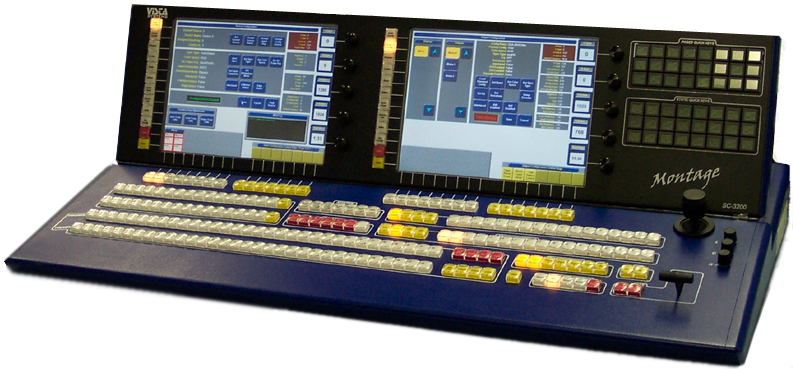
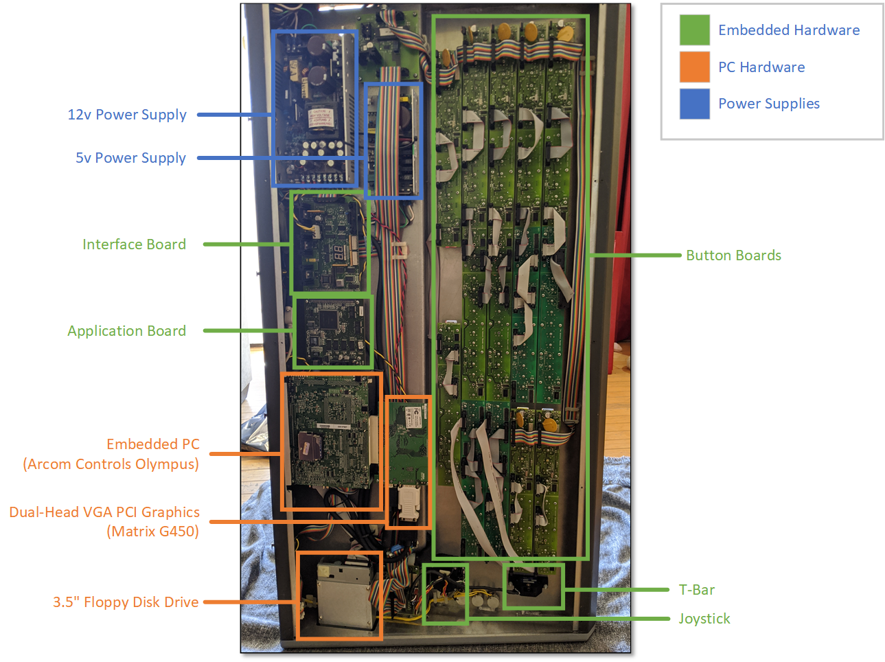
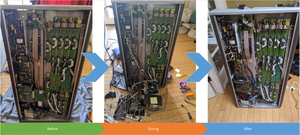
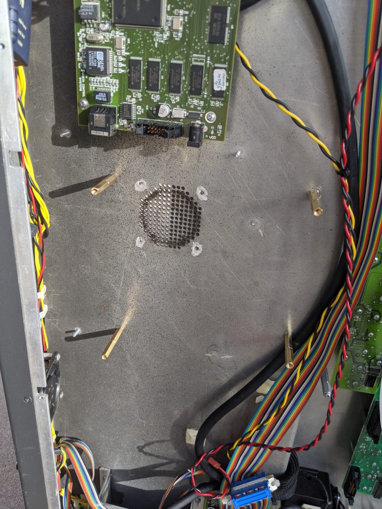
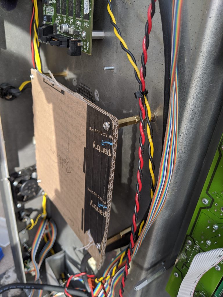
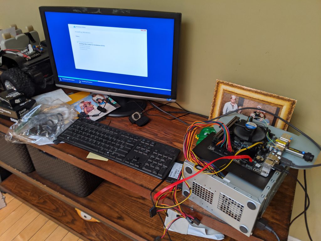
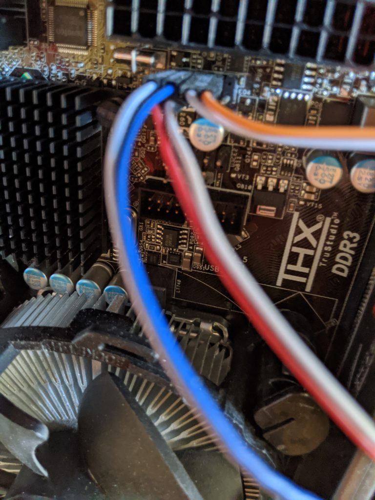
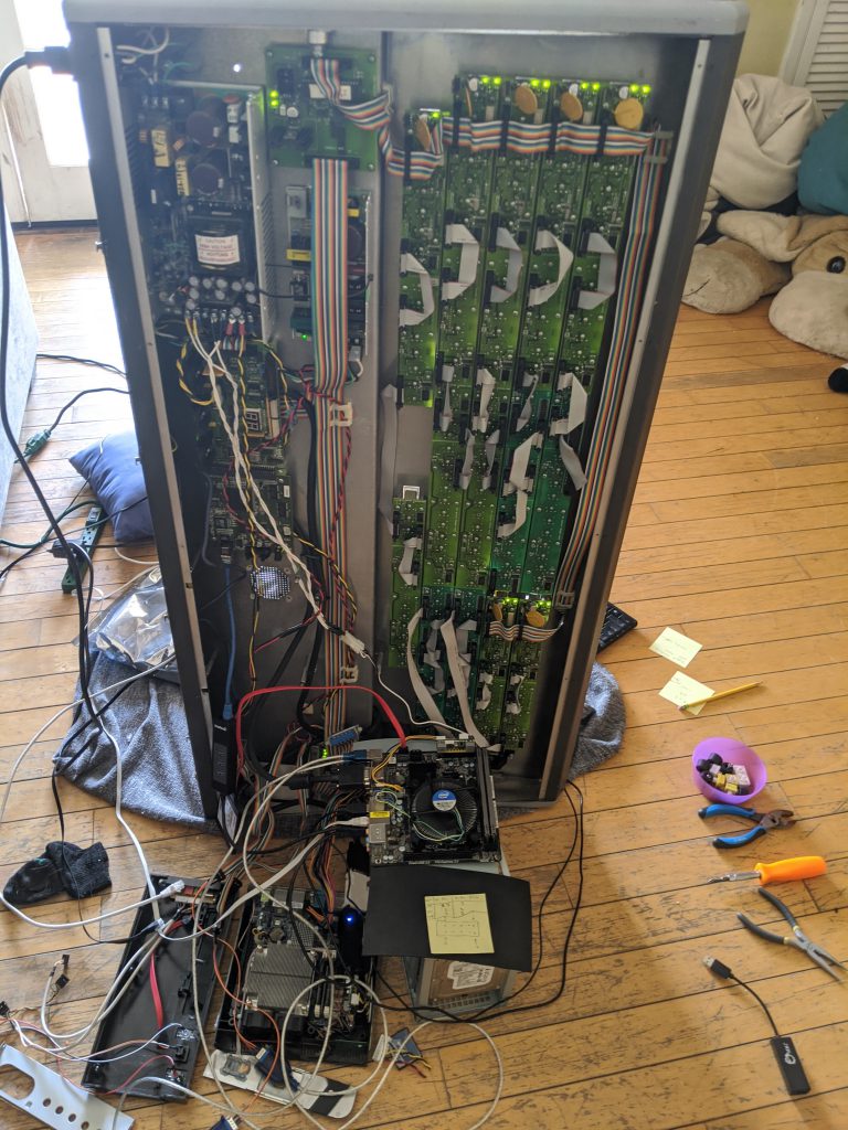
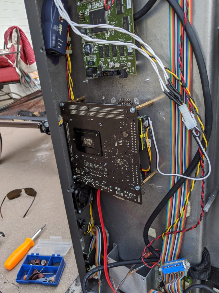
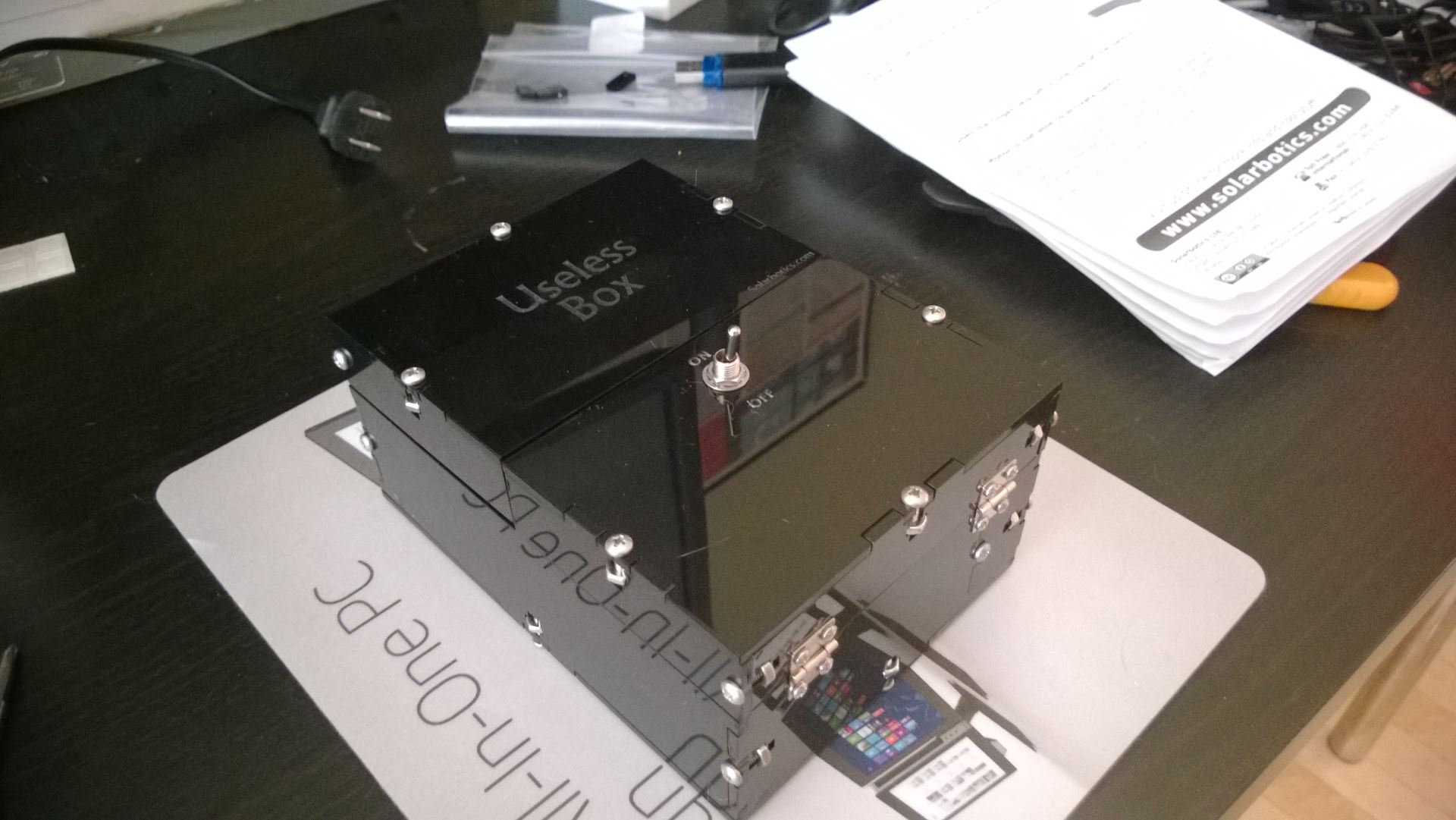
In the first post in this series, we walked through upgrading the internal PC hardware within a ScreenMaster III 3216 hardware controller. In this post, we’re going to start creating the software to communicate between the internal computer and the hardware buttons, joystick, rotary encoders, and T-bar. All of the work discussed in this post lives in a GitHub repository that you can look through and use.

Before we dive in, let’s quickly agree on some terminology. I’m going to refer to the buttons, joystick, rotary encoders, and the T-bar collectively as the ‘keyboard’. Additionally, I’m going to refer to the Windows PC-based computer inside the console as the ‘host’. When we want to turn on or of a lamp for a button, for example, we’ll consider that to be a ‘host’ to ‘keyboard’ communication. Alternatively, when a user presses a key or moves the joystick a ‘keyboard’ to ‘host’ message will be generated. Hopefully this makes sense. Luckily the GitHub repository mentioned earlier in this post uses the same terminology in it’s documentation.

So how do we interact with the console hardware?

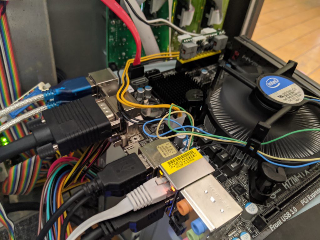
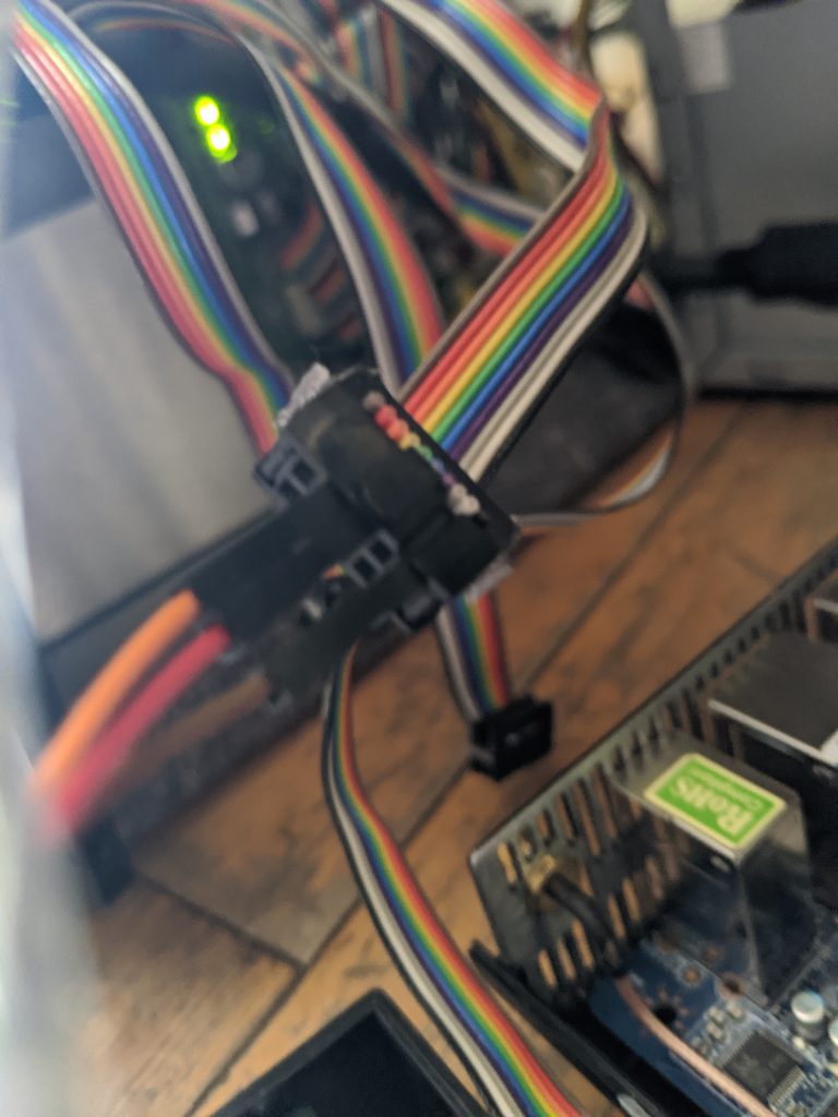
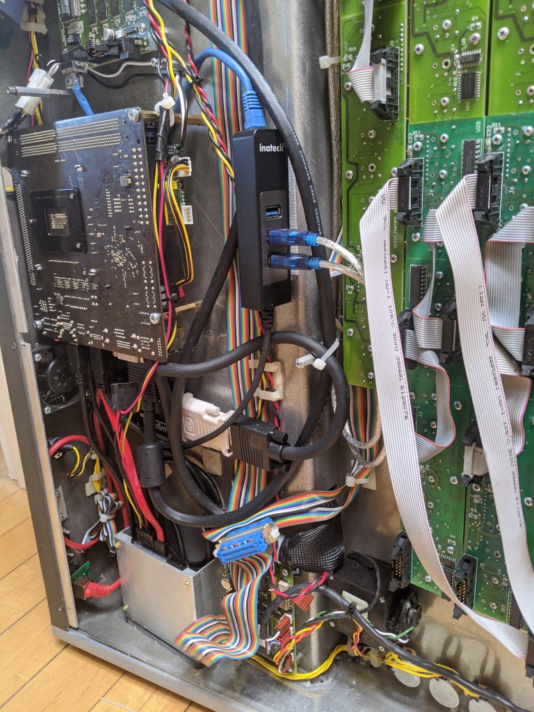
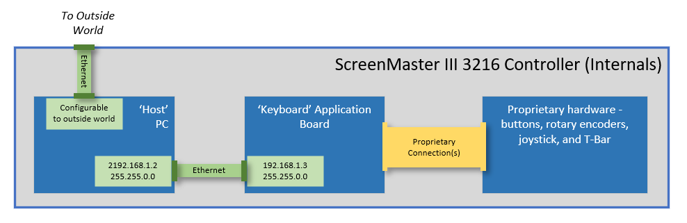
Communication between the host and keyboard is all performed using an internal Ethernet connection. This proved to be extremely helpful when upgrading the hardware, since we didn’t need esoteric connections to interface with the hardware. The keyboard has a hardcoded IP address of 192.168.1.3, and is hardcoded to send event messages to our host computer at the IP address of 192.168.1.2. This is quite limiting, but since it was initially designed to be an internal Ethernet connection we simply added a second USB network adapter during our PC upgrade dedicated to this interface. The image below shows the high-level Ethernet connectivity within the controller:

Over Ethernet, the messages between the host and keyboard are all simple UDP packets, with a very basic structure. I won’t detail the protocol here, but if you’re interested I’ve written up the protocol and published it within the GitHub repo here. Effectively, here’s the main list of things that you can do:

Host to Keyboard:
– Set lamp lights on or off for each button
– Set the LCD button background to Off, Red, Green, or some alternating combination
– Set the LCD button text – 3 lines, 6 characters per line

Keyboard to Host:
– Get event when button is pressed or released
– Get event when the joystick x, y, or z axis value changes
– Get event when a rotary encoder is turned (+/- change value)
– Get event when the T-Bar position changes

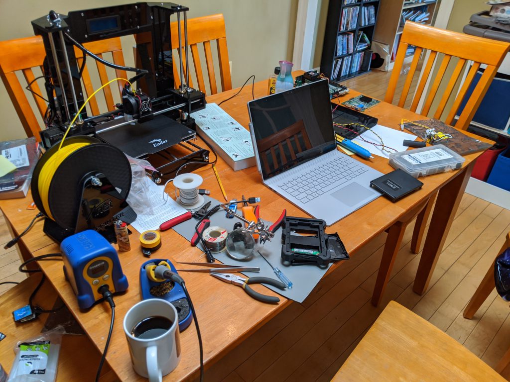
Time to write some software…

I’ve written and published a .Net Standard 2.0 library to implement the keyboard protocol and make it easy to consume from an application. The repository (listed at the beginning of this post) makes it simple to subscribe to events and control the simple pushbutton lights and LCD display buttons.

The repository contains a console test application that subscribes to events and writes these events to the console output. It’s a good example of how to use the library, and I’ve included a snippet of the test program’s Main function below for reference:

using Spyder.Controllers.ScreenMaster3;

static async Task Main(string[] args)
{
    // Initialize connection to keyboard
    var keyboard = new KeyboardInterface();
    await keyboard.StartupAsync();

    // Subscribe to events from the keyboard
    keyboard.TBarValueChanged += Keyboard_TBarValueChanged;
    keyboard.KeyPressed += Keyboard_KeyPressed;
    keyboard.KeyReleased += Keyboard_KeyReleased;
    keyboard.RotaryValueChanged += Keyboard_RotaryValueChanged;
    keyboard.JoystickValueChanged += Keyboard_JoystickValueChanged;
    keyboard.KeyAction += Keyboard_KeyAction;
    Console.WriteLine("Listening for events");

    Console.WriteLine("Press enter to exit");
    Console.ReadLine();

    Console.WriteLine("Shutting down...");
    await keyboard.ShutdownAsync(); 
}

If you’re playing along at home, you can pull down the library and build it from source, or for convenience I’ve also published it as a Nuget package for easier consumption.

Mapping out the buttons

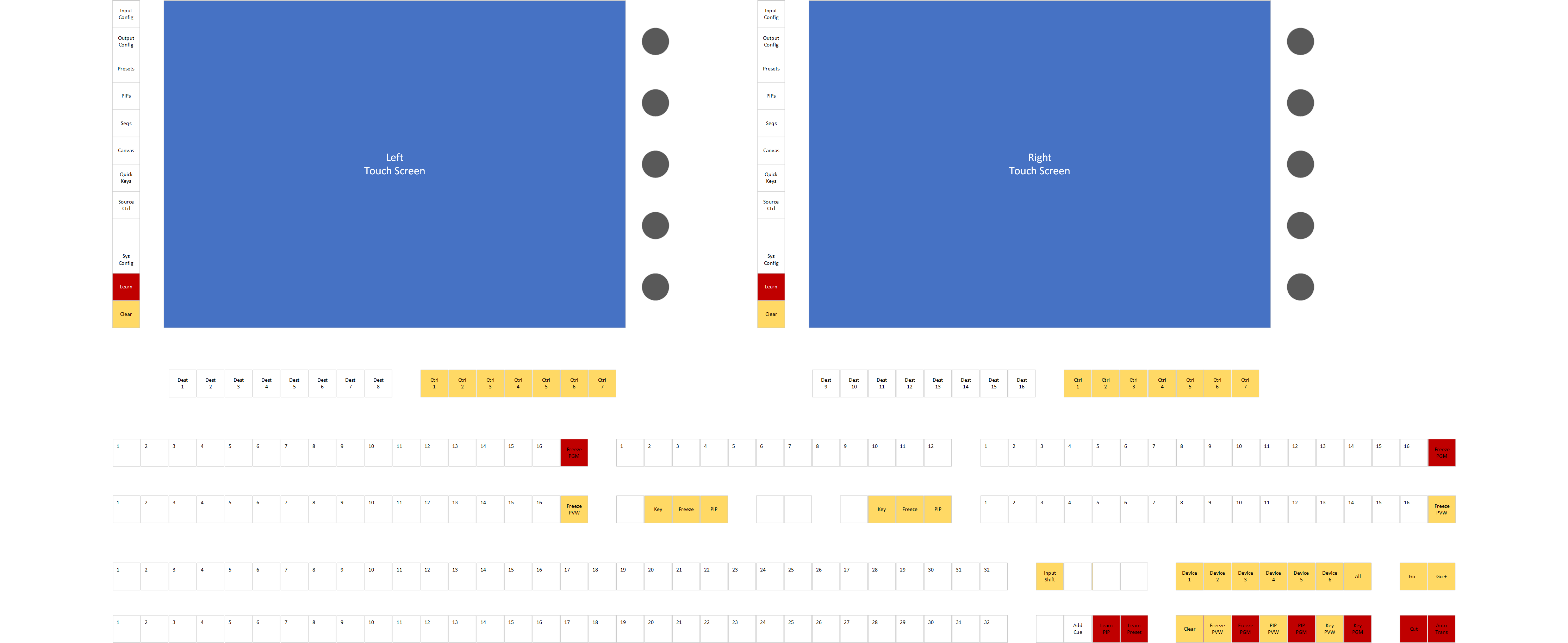
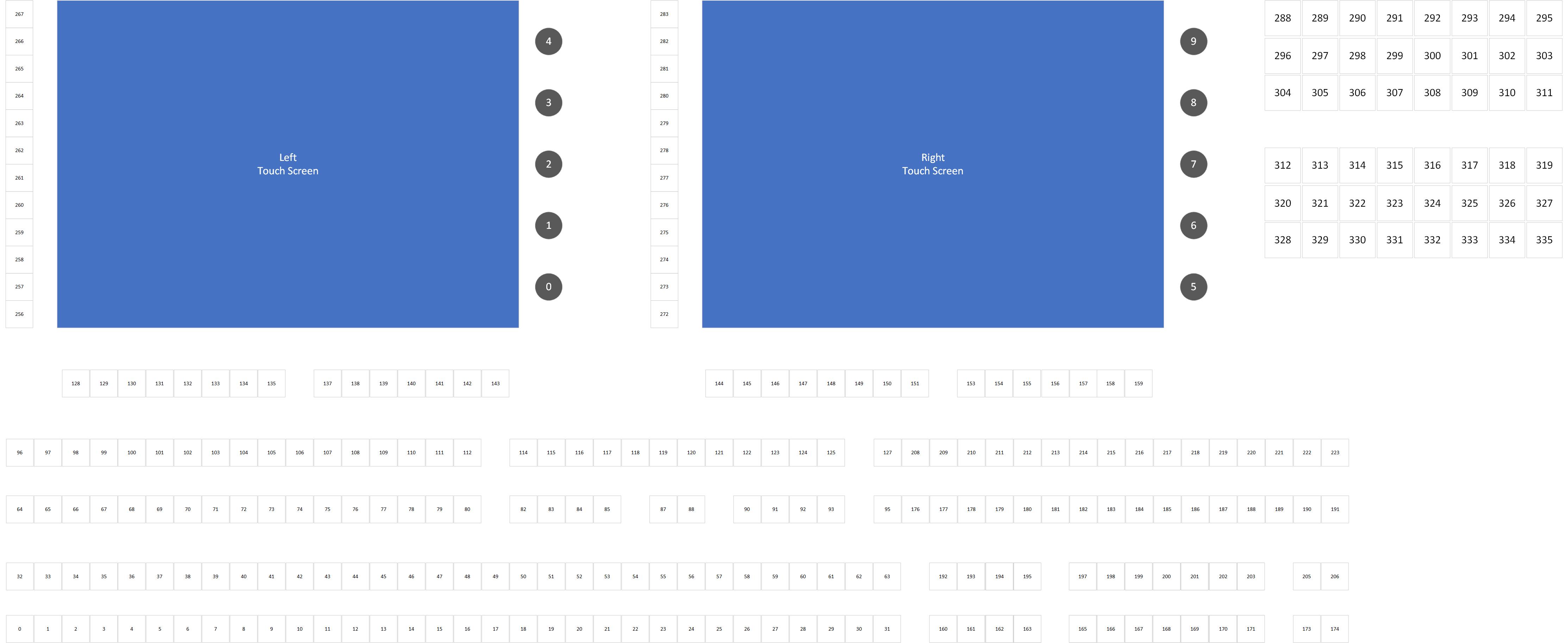
With a software driver library and a test application created, we can now go through the process of pressing and releasing every button on the controller, and watching the event data to determine the logical button ID associated with each physical button and rotary encoder. The console has well over 200 buttons, so it took a bit. My GitHub repo has a Visio document with some different pages that include the index map, and below is an image of this as well as a keycap map for the ScreenMaster III 3216.

Now where are we, and where do we go next?

At this point we have a controller with a modern computer inside, and we have a software library that allows us to interact with the hardware keyboard. With these in place, the real technical challenges are out of the way and we can focus on building an application to control something similarly modern. With my history and existing software libraries and software applications to control Spyder video processors, it’s probably not a spoiler alert to say this is where I’m heading.

I’m not sure yet if the next blog post will be software heavy (yet) – I’m planning to spend some time planning a good console application before diving too far into code. That being said, I couldn’t resist getting some simple app(s) started. As such, I’ll leave you with a quick video showing an app framework that works with the keyboard interface and is setting the selected page based from menu button presses.

If you’re still with me reading through this blog series, thanks! I don’t expect this project to amount to much more than a love letter to an old product that holds nostalgic value to me, but I hope it might resonate with a couple people out there. And if you’re lucky enough to have one of your own ScreenMaster III or a Montage controller lying around, let me know about it!

ScreenMaster III 3216 Console

ScreenMaster III 3216 – Restoring a Classic – Part 1

The ScreenMaster III 3216 and it’s half-sized little sibling the 1608 were some of my favorite consoles every made at Vista Control Systems (later renamed to Vista Systems and later acquired by Christie Digital). These were the first consoles to incorporate 15″ touch screen displays to compliment the massive button boards from prior console generations. This console, like others before it, were purpose built to control a combination of Folsom (now Barco) VFC-2200 scalers and either Extron, Pesa, or Sierra routing switchers. We’re talking analog video only here – this was the nineties after all, when 1080p video was king.

It’s worth a note that this console would be appear again in the future as the control surface for the Vista Montage video processor, painted in blue and re-dubbed as the Montage SC-3200 console. This stuff is all but lost in time, even on the internet these days, and so I’ve included a picture below for full historic reference.

Let’s talk about this got started

Let’s talk about eBay. eBay is a great place to get great deals, and is a great place to troll late nights when you can’t sleep to find stuff you didn’t know you needed (and probably don’t need). One night I happen to be aimlessly looking around the internet, and somehow I made it to this posting on eBay:

This picture of the console immediately gave me ‘the feels’, as it has solid sentimental value. I remember shipping the first of these consoles, sometime back in the nineties. We had a problem with a driver for an internal USB network adapter, and it was causing the console to bluescreen. We weren’t sure it was fixed, but I ‘thought’ I had resolved the issue with an updated driver. We got the console in it’s case and brought it to the back door. After talking a bit about this bluescreen, Jeff Wilson and I opened the console up and made sure it booted successfully five times. As long as it could boot five times in a row, then we’d ship it. Good news – that was the day unit #1 shipped.

<rant>Just to touch briefly on that last point – this was a time when Windows was considered to be generally unstable, and we caught a lot of flack from rental and staging customers (and competitors). Here we were though, shipping a device with Windows (NT Embedded I vaguely recall) and asking customers to entrust their high-dollar live events on it. Software bugs aside, I think this ask proved to be a reasonable one and these consoles were way ahead of their time (my opinion). </rant>

So this console on eBay had an asking price of $599, and I sent an offer for $299 which was accepted. I don’t remember the real figure, but I think this console cost around $45,000 new. From the pictures I could see some button-board activity and a boot failure, and so I knew that (1) the embedded part of the console was alive and (2) the PC was ‘alive’ and the Compact Flash card we used for the hard drive had likely failed. After some back-and-forth on the shipping, we decided to drop the shipping case to avoid going freight, and all-in I think I was down $500.

The arrival

It took about a week for my console to arrive, and it showed up packed tight with instant-foam in a box that must have had a roll of fiber tape for additional support. It took a solid hour to practically chisel the console out of this foam tomb, but it shipped in pristine condition so I can’t complain.

After getting the console freed from it’s shipping cocoon, I gave it a good look over and powered it up. The screen showed the same hard drive failure message that I saw on the eBay post. The quick-keys (the top-right green button array) showed diagnostic counters that I was able to use to verify that the buttons, joystick, T-bar, and rotary encoders were all functional (minus a few burnt-out incandescent switch lamps). So far so good. Next up is to take inventory of the computer hardware and try to get it working again, but before we move on go ahead and take a hard look at that good-looking piece of hardware 🙂 .

Console internals

When you open the bottom of this console, you immediately see that there is a LOT going on. Luckily, when we look closely at the internals of the console there are two main subsystems – the embedded computer (PC) and the physical control interface (buttons / T-Bar / Joystick) subsystem. The picture below shows the console on it’s side with the bottom removed.

The application board is the main embedded component which houses the programming required to read and write the physical hardware. Luckily for us, the interface between the embedded computer and this application board is Ethernet. It’s difficult to see in the pictures, but there is an Ethernet crossover cable between a second Ethernet port on the SBC and the application board. This is great, because it means that we can upgrade the embedded computer without worrying about obscure hardware interface dependencies.

Before we move on to replacing the embedding computer, let’s take a second to talk about the embedded computer that came with the console. This was an EBX form factor computer called the ‘Olympus’ and was manufactured by Arcom Controls (datasheet here). This was a 1.0 Ghz Celeron processor and 128MB of RAM. The hard drive was provided with a 128MB Compact Flash card, which has limited read/write cycles and almost certainly explains why the console eventually stopped working. I did try jump-starting the console with a new Compact Flash module, but the SBC was so old that it felt that even if I could run a modern operating system on it (unlikely) that it would be terribly slow. It was also sporting a 3.5″ floppy disk drive, for those of you who remember what that even is, and I knew that needed to be brought into the modern age as well. With that back-story out of the way, let’s get to upgrading.

Upgrading the Embedded Computer Hardware

Full disclosure here – this console sat on it’s side in my living room for several weeks, and I’d give it occasional blocks of evening and weekend time. This wasn’t particularly hard, but there were some time-consuming parts of the effort that I’ll bullet point rather than writing a book about:

  • Removed the prior EBX form-factor PC board and graphics adapter
  • Removed the existing floppy disk drive
  • Drilled holes in the chassis to fit a new Mini-ITX form factor PC
  • Bought a +12V to ATX power adapter module to power the new SBC
  • Added two USB to RS-232 cables to drive the touch screens
  • Added a USB to Analog adapter to drive the second touch screen (the SBC had one VGA port I was able to use as well)
  • Replaced the Neutrik Ethernet connector running to the back of the console with a new one
  • Modeled and 3D Printed a custom bracket to hold a new Solid State hard disk and expose 2x USB 3.0 ports to fit in the old floppy disk drive spot.

The mounting and retro-fitting of the new SBC and parts was a pain, but I’m pretty happy with how it came out. This thing feels like it could travel and be as reliable as the original console was. I am particularly proud of the 3D printed module that I made to hold the hard drive and expose a couple USB ports, and you can see this along with a bunch of other build pictures below

After the aforementioned evenings and weekends spanning may weeks, the hardware for the console was done. It was now sporting an Intel i7 processor with 16GB RAM and a 512GB solid state disk, and was running quite nicely. I did sneak in a picture of installing Windows on the replacement Embedded PC / Single Board Computer (SBC), but I’ve saved this for the last section of this post.

Let’s put Windows 10 on this thing

A modern console needs a modern operating system. I actually considered installing Ubuntu Linux for the fun factor, however ultimately I decided to install Windows 10 Pro. It’s less ’embedded’, but it allows for wider flexibility for software to run (including Vista Advanced / Spyder Studio / Spyder Client software).

One wrinkle that I did run into was around the touch screens. They have RS-232 serial controllers, and the native 3M driver didn’t work. I remember running into this with my Car computer touch screen (same hardware), and so I knew I needed to pony up and buy a license for a software called touch-base that makes the touch controllers work with Windows 10. Related note – the screens for the console are each 1024×768 resolution and VGA, and if I were braver I would crack open the top and try to replace them with some newer displays. Maybe someday.

Big reveal time

I don’t need a lot of words for this – I’ll let the pictures of the console working speak for themselves. For those curious, the pretty looking Spyder control software is the Spyder Client application that is available on the Windows 8/10 Store.

So where are we, and what’s next?

So we have a large powerful hardware console alive and well, and we have a working PC operating system on it. Probably a way over-powered PC in there hardware spec-wise, but we still don’t know what we’ll do with it so hard to say. By the time I write this, the console has actually been sitting in my dining room for the past two months. I’ve already done some development and created a software interface to integrate the hardware with the PC, but I’ll save that for a future blog post.

In the next post, I’ll talk about how the PC-to-embedded hardware interface works, and we’ll probably have a simple app to show take a look at. I expect the next post will be a bit shorter – this one was a monster and it feels like it just skims the surface. With that, thank you for reading and see you next time!

The Useless Box

You know, I’d argue that a box that makes you smile hardly qualifies as useless.  Nevertheless, today I finished assembly on the self named ‘Useless Box’ by solarbotics.com.  This black acrylic box has a single switch on it’s top, which when flipped, turns on a motor connected to a ‘finger’ which pops up and flips the switch back to the off position.  I’ve found myself flipping it on at my desk almost instinctively throughout the day, and it makes me smile every single time.  It’s just simply great.  Take a look at the video to get a better idea of what we’re talking about here.

 Assembly

Assembling the useless box is not hard, but it is a little time consuming, and does require you to solder a small amount of stuff together.  Honestly I think I spent half as much time peeling the protective brown paper off all the parts as I did doing the rest of the assembly.  Here is how your useless box arrives:

Raw materials for a Useless Box

Raw materials for a Useless Box

The assembly breaks into four or five steps, each taking about an equal amount of time.  The instructions estimated 1.5 hours for the full build, but it took me more like 2.5 hours (yes I’m slow).

Build Steps:

  1. Remove all the damn brown protective paper from the acrylic parts.
  2. Solder together the electronics.
  3. Assemble the main box.
  4. Disassemble and then re-assemble the box after you figure out that the piece holding the motor needs to be mounted as the rest of the box is being put together.
  5. Mount the electronics in the box, adjust for fit, and then test!

The electronics harness would have been much easier if I still had a vice to hold the parts in place while trying to solder, but a little scotch tape did the trick in a pinch.  Below is the finished electronic harness and the box parts all laid out:

Assembled electronics harness and box parts

Assembled electronics harness and box parts

And here is the finished product:

Useless box assembled product

Useless box assembled product

Call to Action: Go Buy One

This thing is fun, and is worth plunking down some cash for.  I’m sure you can get it at a number of places, but mine came from ThinkGeek, which is a site I believe you should be giving your money to anyway.  Below is the link; you’ve seen it in all it’s glory, now take one home for yourself.  It’s great for your desk at work and your home, so maybe get two…

Go buy the Useless Box at ThinkGeek