A whole 7 years ago I published a blog post and a couple YouTube videos showing a cool Tally (camera relay) system that anyone could make with a $35 Raspberry Pi device and $10 relay board. Back then this was running Windows on the Raspberry Pi 2 – a special stripped-down version of Windows called IoT Core that was designed to run on the Pi.
In seven years, a lot has changed. I started sprouting some gray hairs, Microsoft has all but abandoned Windows IoT Core on the Pi, .Net Core has become a mature way to deploy applications on Linux, and the Pi itself has had a powerful version 4 on the shelves for almost two years now. In this blog post, we’re going to modernize our prior approach and add some cool new features like a front panel display and a configuration/monitoring web interface.
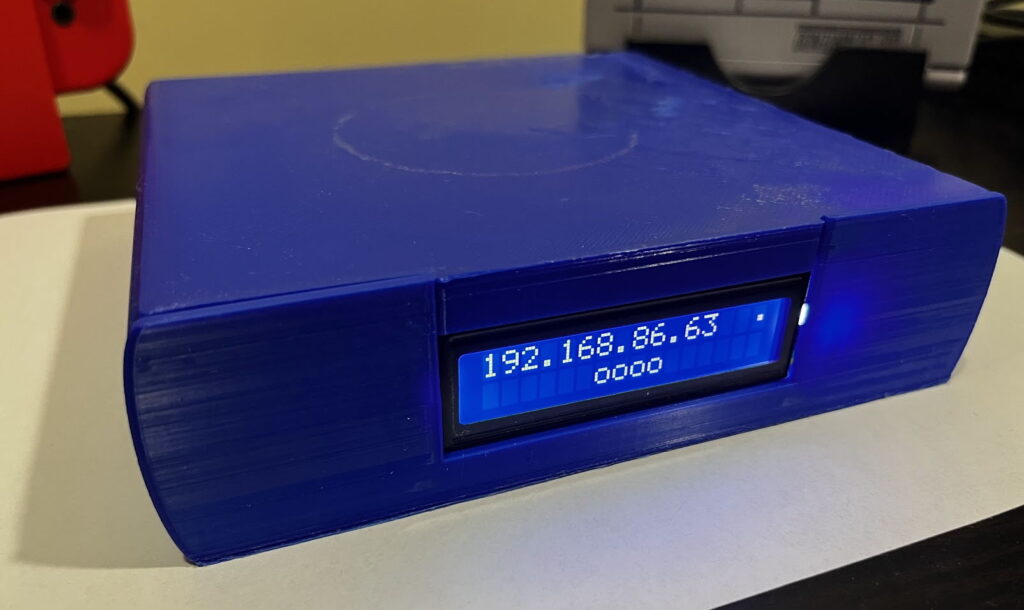
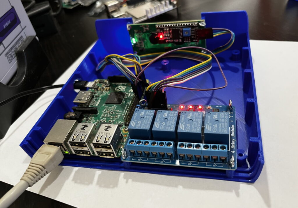
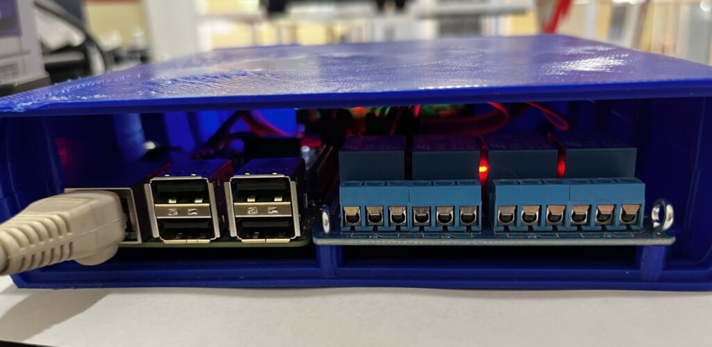
Features and Overview
- Works with Spyder 200 / 300 / X20 / X80 hardware
- Works with every major release version of Spyder software
- Supports different servers and rules per individual tally
- Built-in web server for remote configuration and monitoring
- Front panel shows device IP and on/off tally icons for quick viewing of status
If you have a Spyder video processor of any generation, this device will work as a tally controller. For those wondering what tallies are, imagine a live show where multiple cameras are pointed at talent on a stage. Lights are usually physically positioned on top of the cameras and light up when a camera is ‘live’ to help the talent know which camera they should be looking at. The tally controller described here contains relays (electronically controlled contact closures) which open and close when specific sources are shown or hidden in windows on Spyder.
The video below walks through the device hardware and software, providing probably a better end-to-end overview than this blog post for those of us out there who prefer to consume video content.
Parts you Need
First off, you’re going to need to buy some parts. Here’s a list of what you need, some of which you may have around the house:
- ($8 – $15) Either a 4-Port Relay board or an 8-Port board (lot of wiggle room on options here)
- ($35+++) Raspberry Pi 2, 3, or 4. They should be $35, but the chip shortage has these well up over $80 as of the time of this writing.
- ($19) A good SD card for running a Raspberry Pi OS. Resist the urge to go cheap here, as cheap SD cards tend to burn out relatively quickly.
- ($25) If you have a 3D printer, you can pick up a spool of ‘Spyder blue’ filament. If you don’t have a 3D printer, you can use a service like Xometry and have it printed for you for about $300 (honestly just go buy a cheap 3D printer).
- ($10) Blue I2C LCD display module for our front panel
- ($8) Panel mount USB Micro cable to bring the power connector from the Pi to the back of the unit. If you use a Raspberry Pi 4, use a USB-C variant of this cable
- ($12) Raspberry Pi Power Supply (Micro-USB for Pi 2 or 3, or use USB-C for a Pi 4)
- ($6) Female-to-Female wire kit to connect the parts together
3D Printing a Chassis
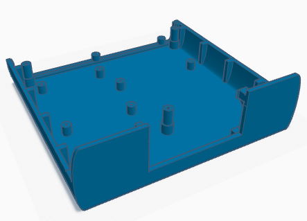
I used TinkerCad to design a simple chassis to hold a 4-relay board. You can copy and modify this design as you see fit, but for most folks you can simply download the 3D print STL files for the top and bottom pieces, and either print them yourself or send them off to a 3D printing service. If you watch the video from earlier in this blog post you’ll see the Raspberry Pi and the tally board are on the wrong sides of the chassis, and I’ve corrected this in the current design.
| Chassis Top Piece | Chassis Bottom Piece |
|---|---|
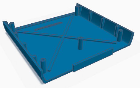 |  |
| View in TinkerCad | View in TinkerCad |
Building the unit is quite easy once you’ve acquired and printed the parts required. The open frame views in the video show off mounting the raspberry pi, tally board, and LCD front panel display in the chassis.
Wiring the pieces together
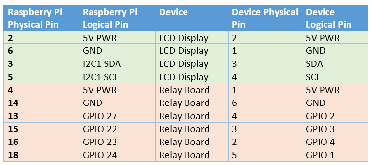
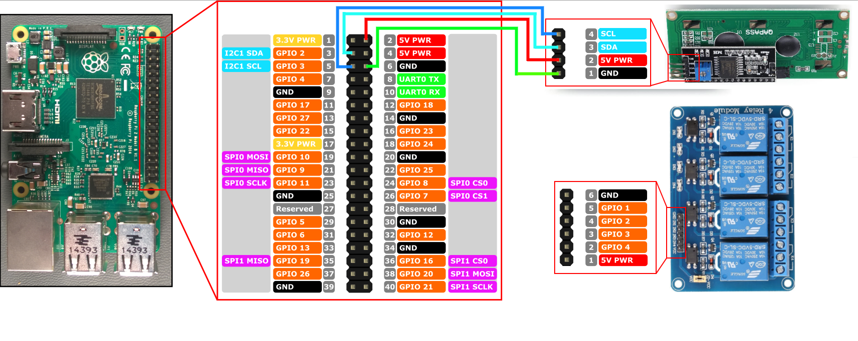
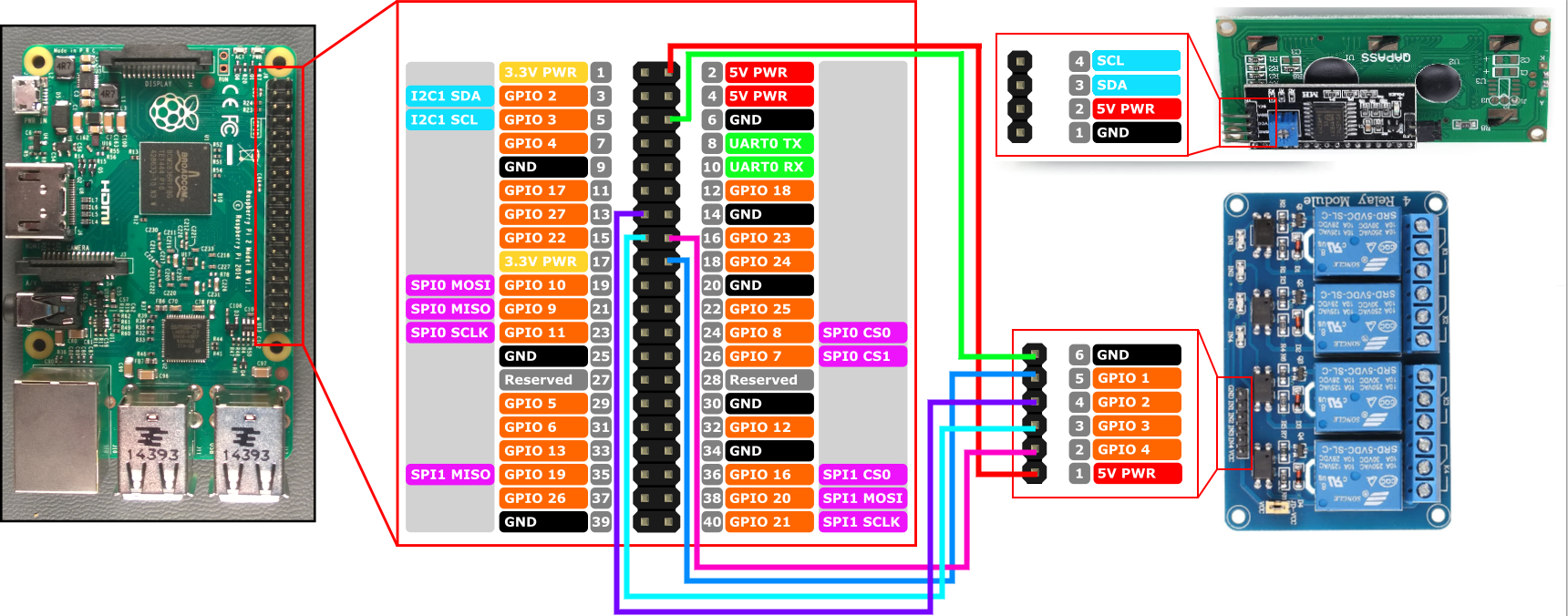
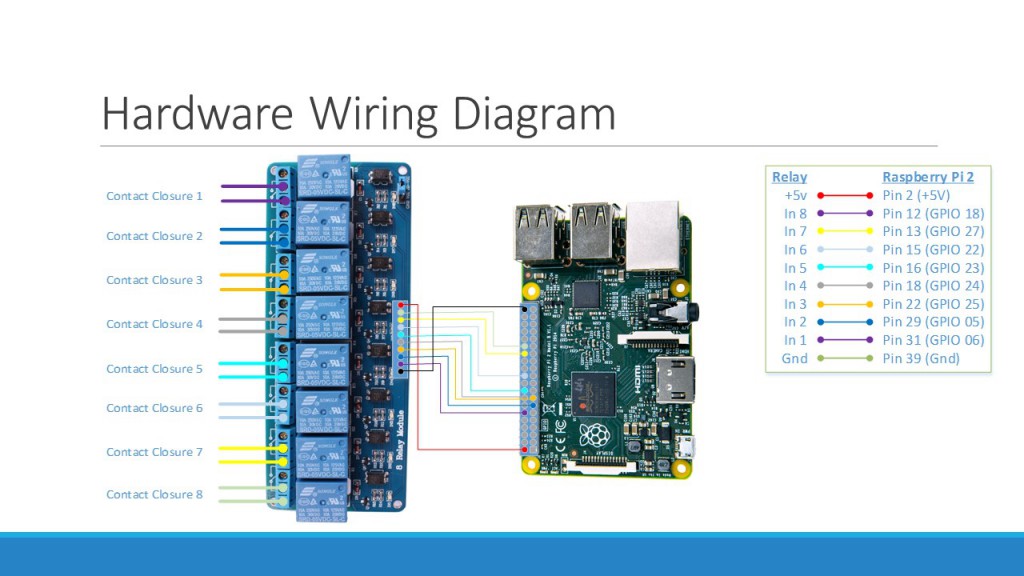
You can use simple breadboard style wiring connectors to save yourself from any kind of soldering, making the assembly a ‘Lego-like’ plug and play experience. The images below show the connections you’ll wire up from the Raspberry Pi to the LCD display and the relay board. If you’re creating a tally controller with more than the 4 relays shown, you’ll simply pick some more GPIO ports on the Pi for the additional connections (just be sure to write down which pins are connected to the relay pins for later configuration).
Installing the Pre-Built Raspberry Pi Software
Download SD Card Image for Raspberry Pi and/or release binaries here
Installing the pre-built software image for the Raspberry Pi is the easiest way to get going. You can download the SD card image directly from the Spyder Tally GitHub project’s releases page and use the official Raspberry Pi Imager tool to write that image file onto an SD card.
After writing the image file to the SD card, insert it into the Raspberry pi, connect an Ethernet (network) cable and power it up. It shouldn’t be necessary to connect a monitor to the Pi, but it does feel nice to keep an eye on it during the first boot where it will perform one-time tasks like expanding the file system to fill the SD card. That first boot will take several minutes, but eventually you should see the front panel light up and show the unit’s IP address.
Note that the software will wait for the network to become available before launching, and so you will not see anything until after the network is plugged in.
Installing Manually (Raspberry Pi or Other Devices)
If you’d like to use a device different than the Raspberry Pi, or if you want to build your own Raspberry Pi image for whatever reason, you’re in luck because it’s easy to do! The software may need some tweaking (particularly around hardware interface control) but should readily run on a wide variety of Linux devices including x86, x64, and ARM hardware with minimal tweaking.
The steps involved in creating your own disk image can be extrapolated from this README up on the project’s GitHub site.
One tweak I made when building the v1.0.0 SD card image – instead of installing the .Net Core framework on the device, I compiled the app as a ‘self-contained’ deployment. This kind of deployment bundles in all the .Net runtime pieces needed to run the application, and can both slim down the overall disk footprint and decouple the app from needing to be deployed on a target with a compatible .Net framework version. I like this approach and will likely continue this trend in future releases.
Summary
Spyder is an excellent product, and I’ve always been proud to have been a part of its history during my years at Vista / Christie Digital. Making accessory software and devices like this tablet controller still make me incredibly happy even years later. I hope you enjoy making your own as much as I enjoyed creating it. Let me know what cool environments you end up using it in!
If you run into any snags or have ideas for improvement on the project, the easiest way to communicate is to file issues up on the project’s official GitHub repository issue tracker. I do keep an eye out for comments and will try to reply as I can, but I tend to have a bad habit of not checking for comments for months at a time 🙂
